Loading Port:China main port
Payment Terms:TT OR LC
Min Order Qty:1 set
Supply Capability:1 set/month
Profile
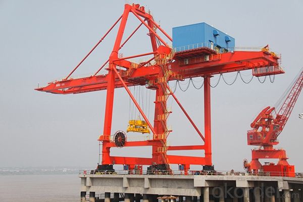
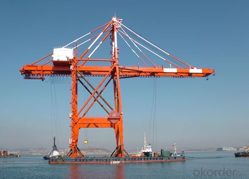
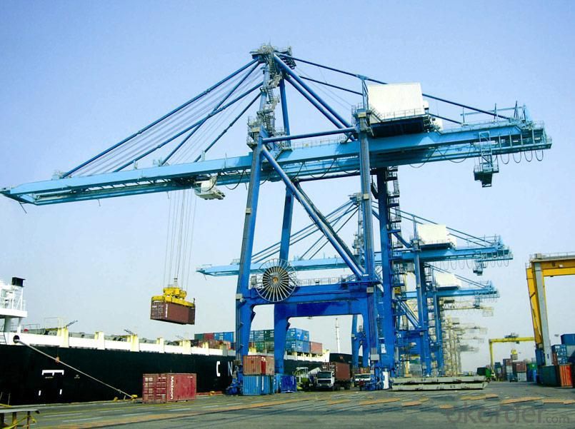
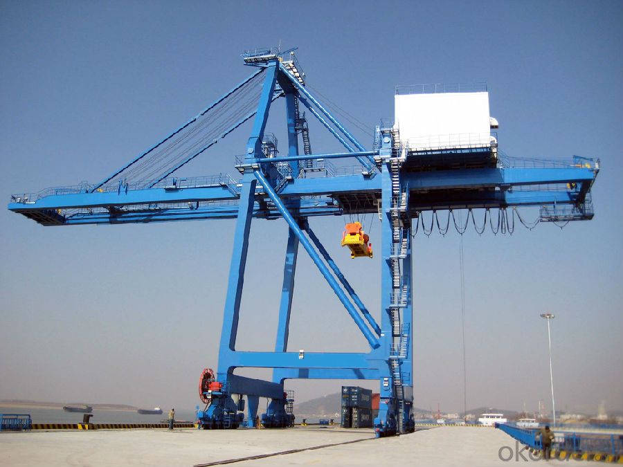
Quayside Container Crane (Ship-to-shore gantry cranes) are designed and manufactured according to the ‘design rules for cranes’, the international current design and manufacturing standards and codes as well as the advanced foreign standards such as FEM, DIN , IEC, AWS and so on.
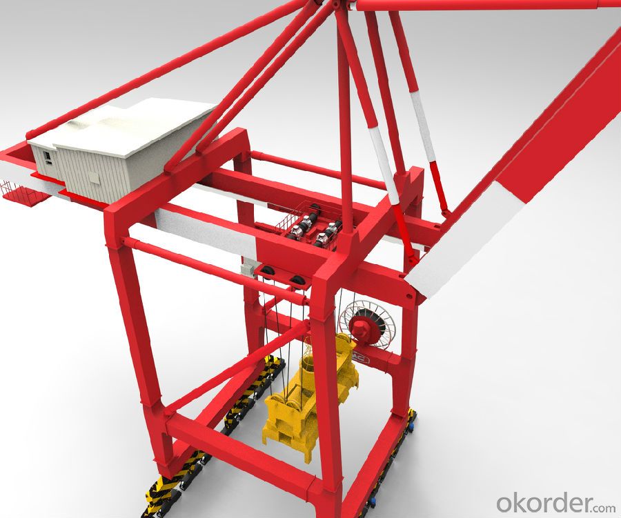
The quayside container crane is mainly composed of electric control system, steel structure, machine house, main hoisting mechanism, traversing mechanism, travelling mechanism, boom hoisting mechanism. Trolley assembly, maintenance crane, rotating mechanism, anti-snag protection devices. The advanced A.C variable frequency speed control techniques are used for the main hoisting mechanism, traversing mechanism, travelling mechanism and boom hoisting mechanism. The crane is also fitted with advanced single lift or double lift spreader with different specification and has mechanical or electronic anti-snag function. Up to now, the main specifications are 35t, 41t, 51t, 65t.
Technical Parameters
35t/41t Quayside Container Crane | |||||||
Rated Lifting Capacity | Under Spreader | 35 | 41 | t | |||
Under Hook | 45 | 50 | t | ||||
Lifting Height | Above Rail Surface | 37 | 25 | 50 | 35 | m | |
Below Rail Surface | 12 | 15 | m | ||||
Outreach | 30 | 45 | m | ||||
Backreach | 10 | 15 | m | ||||
Gauge | 16 | 16/22 | m | ||||
Total Trolley Travel Distance | 56 | 76/82 | m | ||||
Inside Clearance Between Legs | ≥16.5 | ≥17 | m | ||||
Clear Height of Middle Cross Beam | ≥13 | ≥13 | m | ||||
Distance Between Gantry Bumpers | ≤27 | ≤27 | m | ||||
Lifting Speed | Full Load | 50 | 60 | m/min | |||
Empty Load | 120 | 120 | |||||
Trolley Travelling Speed | 180 | 210 | m/min | ||||
Cart Travelling Speed | 45 | 45 | m/min | ||||
Boom Hoist Time One Way | 5 | 5 | min | ||||
Technical Parameters
51t/65t Quayside Container Crane | |||||||
Rated Lifting Capacity | Under Spreader | 51 | 65 | t | |||
Under Hook | 61 | 75 | t | ||||
Lifting Height | Above Rail Surface | 58 | 40 | 62 | 42 | m | |
Below Rail Surface | 18 | 20 | m | ||||
Outreach | 51 | 65 | m | ||||
Backreach | 15 | 25 | m | ||||
Gauge | 30.48 | 30.48 | m | ||||
Total Trolley Travel Distance | 96.48 | 120.48 | m | ||||
Inside Clearance Between Legs | ≥18.5 | ≥18.5 | m | ||||
Clear Height of Middle Cross Beam | ≥13 | ≥13 | m | ||||
Distance Between Gantry Bumpers | ≤27 | ≤27 | m | ||||
Lifting Speed | Full Load | 75 | 90 | m/min | |||
Empty Load | 150 | 180 | m/min | ||||
Trolley Travelling Speed | 240 | 240 | m/min | ||||
Cart Travelling Speed | 45 | 45 | m/min | ||||
Boom Hoist Time One Way | 5 | 5 | min | ||||
Composition
-Lateral movement system:
A combination of two sets of typically ten (10) rail wheels. The lateral movement is controlled by a cabin along the land side wheel. During any lateral movement, lights and sirens operate to ensure safety of the crew operating adjacent to the crane. The wheels are mounted to the bottom of the vertical frame/bracing system.
Vertical frame and braces:
A structurally designed system of beams assembled to support the boom, cabin, operating machinery, and the cargo being lifted. They display signage describing restrictions, requirements and identifiers.
-Crane boom:
A horizontal beam that runs transversely to the berth. It spans from land side of the land side rail wheels to a length over the edge of the berth. The waterside span is based on the size of ship that it can successfully load/unload. Beams also have the ability to be raised for storage purposes.
-Hook:
Device which moves vertically to raise and lower cargo as well as horizontally along the boom's length. For container cranes, a spreader is attached to span the container and lock it safely in place during movement.
-Operating cabin:
Encased setup with glass paneled flooring for operator to view the cargo being moved. Elevators which are located along vertical frame members are used to get crew up and down from the cabin.
-Storage Equipment:
For temporary storage options between vessel operations, one steel pin is inserted into anchorage arm dropped from each wheel set into a stow pin assembly. This setup is designed to prevent lateral movement along the rails. During hurricanes and other emergency shut down situations, tie down assemblies are used. Two (2) angled arms are anchored at each end of each set of wheels. This setup prevents longitudinal movement along the rails as well as prevents tipping of the crane due to uplift from high velocity winds.
Ship-to-shore gantry cranes are often used in pairs or teams of cranes in order to minimize the time required to load and unload vessels. As container ship sizes and widths have increased throughout the 20th Century, ship-to-shore gantry cranes and the implementation of ship-to-shore gantry cranes has become more unique in order to effectively load and unload vessels while maximizing profitability and minimizing time in port. One example are systems where specialized berths built that accommodate one vessel at a time with ship-to-shore gantry cranes on both sides of the vessel. This allows for more cranes and double the workspace under the cranes to be used for transporting cargo off dock.
Technology Developments
Quayside container crane is constantly updated with the vigorous development and technological progress of container ships, especially in the development of super Panama ship type, the crane put forward newer higher requirements. One is to improve the technical parameters of crane, makes the crane speed higher, the distance of extension and the height of hoisting are increased, lifting rated lifting capacity of spreader are increased; Two is to develop and design efficient quayside container handling system, in order to meet the requirements of large ship crane productivity.
