Loading Port:China main port
Payment Terms:TT OR LC
Min Order Qty:1 set
Supply Capability:10 set/month
Profile
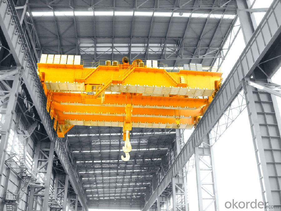
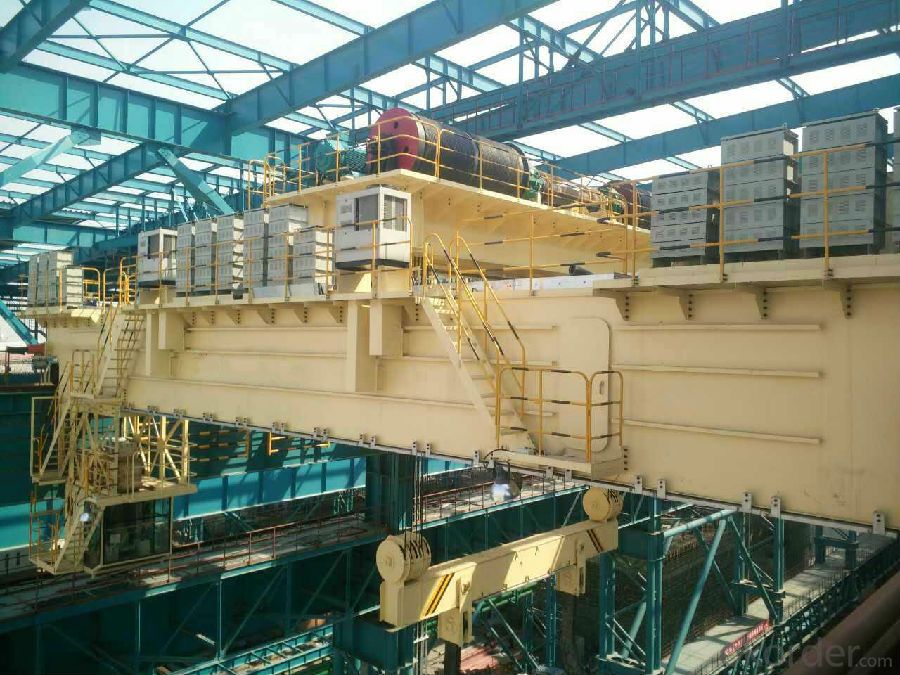
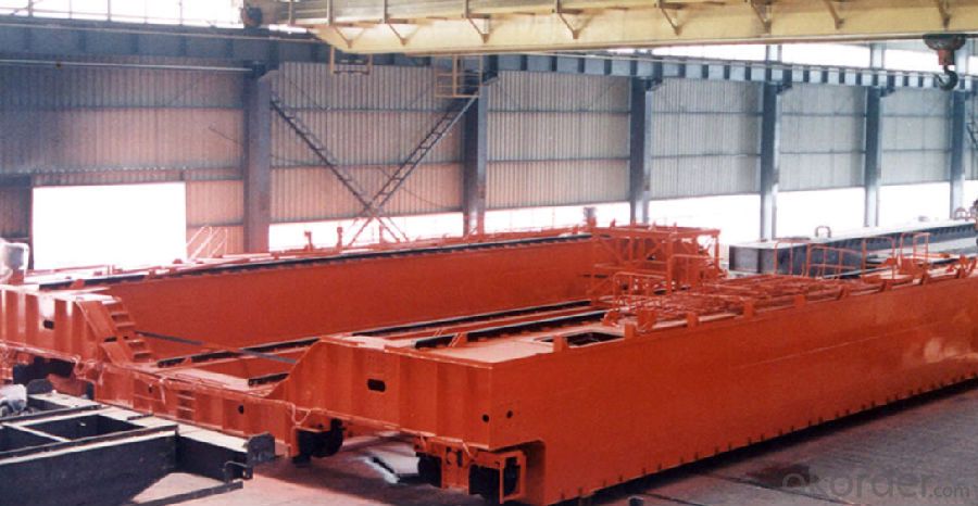
YZ Model 80-320t Foundry Overhead Crane is one of the main equipment in steelmaking and continuous casting process. It is mainly used for converter, charging, cross converter and hot metal charging. The steel water is lifted to the refining furnace from refining span during the refining process, or the steel water is lifted from steel water span to the continuous casting rotary ladle.
The overall structure of the foundry overhead crane can be divided into: double beam with dual rail, four beam with four rail, four beam with six rail and so on. Double beam with dual rail and four beam with four rail are usually used in medium or large tonnage foundry crane; Four beam with six rail and trolley are usually used in large tonnage foundry crane.
Features
- The main hoisting mechanism is equipped with two sets of driving devices. When one of the motors or an electronic control unit fails, another drive unit should be able to ensure that a working cycle is completed at rated lifting capacity.
-Four wire rope winding system of main hoisting mechanism. When one of the two ropes is located on the diagonal, the stability of the tank can be ensured, and the tilting and falling accidents of the tank can not occur.
-The main beam adopts wide with side rail box beam, which has good vertical and horizontal stiffness. In order to avoid the fatigue failure of the main beam caused by the concentrated wheel pressure, the T steel is used under the rail, which greatly improves the life of the main girder.
-The main mechanism and the main electric control equipment are all installed in the main beam. The whole structure is compact and the shape is beautiful.
-According to the needs of customers, the following functions can be provided:speed of each mechanism can be adjusted (1:10 or greater), rotary spreader and hook of gantry can change the variable distance, etc.
Technical Parameters
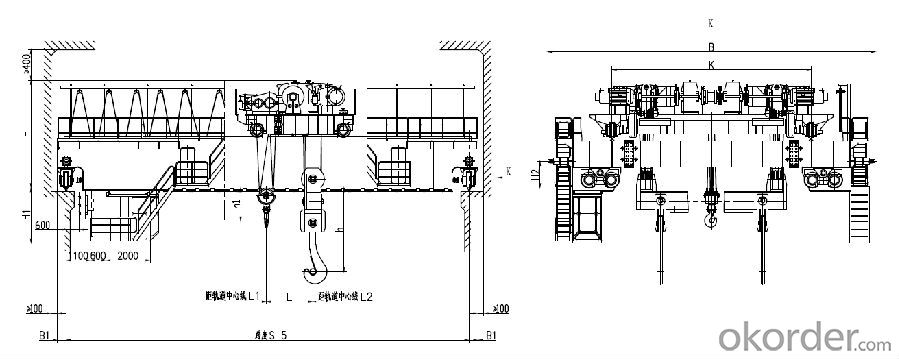
-YZ Model 80/20-100/32T Double Beam Foundry Crane
Lifting Capacity(t) | 80/20 | 100/32 | ||||||||
Working Class | A7 | A7 | ||||||||
Span(m) | 19.5 | 22.5 | 25.5 | 28.5 | 19.5 | 22.5 | 25.5 | 28.5 | ||
Lifting Height(m) | Main Hook | 20 | 20 | |||||||
Aux. Hook | 22 | 22 | ||||||||
Speed(m/min) | Main Hook | 6.3 | 7.5 | |||||||
Aux. Hook | 9.7 | 10.5 | ||||||||
Trolley | 38.7 | 38 | ||||||||
Cart | 67.6 | 77 | ||||||||
Main Size(mm) | L1 | 1500 | 1600 | |||||||
L2 | 1800 | 2200 | ||||||||
L | 2150 | 2500 | ||||||||
h | 3700 | 3500 | 4000 | |||||||
h1 | 1660 | 1460 | 2300 | |||||||
H | 4300 | 4500 | 4900 | |||||||
H1 | 2745 | 2600 | 2700 | |||||||
B | 13900 | 14500 | ||||||||
K | 8500 | 9200 | ||||||||
B1 | 400 | 410 | ||||||||
Max. Wheel Pressure(KN) | 399 | 415 | 425 | 440 | 486 | 516 | 540 | 560 | ||
Steel Track | QU120 | |||||||||
Power Supply | AC380V 50HZ | |||||||||
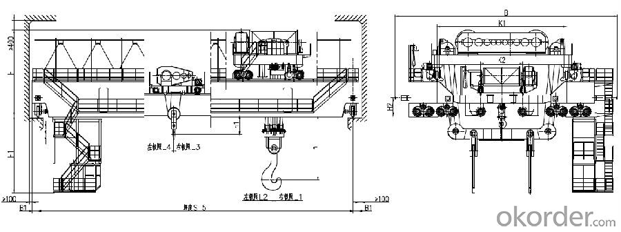
-YZ Model 280/75-320/80T Four Beam Foundry Crane
Lifting Capacity(t) | 280/75 | 320/80 | |
Working Class | A7 | A7 | |
Span(m) | 21 | 24.5 | |
Lifting Height(m) | Main Hook | 24 | 28 |
Aux. Hook | 26 | 32 32 | |
Speed(m/min) | Main Hook | 10 | 9 |
Aux. Hook | 10.5 | 10 | |
Trolley | 36 | 36 | |
Cart | 39 | 39 | |
Lifting Capacity(t) | 76 | 63 | |
Main Size(mm) | L1 | 3200 | 3300 |
L2 | 3500 | 3500 | |
L3 | 2500 | 2500 | |
L4 | 2000 | 2000 | |
h | 5900 | 6000 | |
h1 | 1800 | 1800 | |
H | 7600 | 7800 | |
H1 | 5000 | 5000 | |
B | 19200 | 19500 | |
K1 | 12000 | 12500 | |
K2 | 3800 | 5000 | |
B1 | 500 | 500 | |
Max. Wheel Pressure(KN) | 595 | 650 | |
Steel Track | QU120 | ||
Power Supply | AC380V 50HZ | ||
Technical Specification
- Bridge Frame
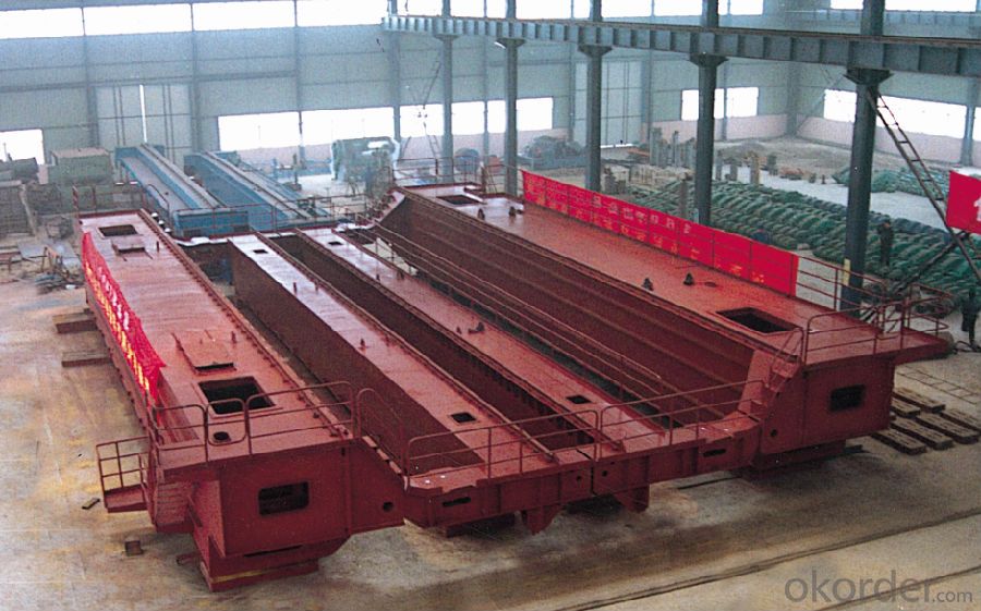
The main beam adopts wide flange box structure with side rail, and carries out finite element analysis and calculation in strict accordance with the working level of the crane, so that it has good strength and stiffness under the vertical, horizontal and torsional loads. The main beam is made of Q345B material. Set up electrical room in the middle of the main beam and place electrical control equipment. Sealed door are installed at both ends of the electrical room to prevent dust and heat invading the electrical room and affecting the work of the electrical components. The electric room adopts the measures of heat insulation and radiation protection to reduce the influence of outside heat baking. The end beam adopts box structure, and the side and the upper of the end beam are respectively provided with railings and cable grooves. The end beam is made of Q345B material.
-Main Hoisting Mechanism
The main hoisting mechanism consists of double motor, double reducer, four brake, double drum group, coupling, pulley block, over speed switch, limit switch and so on. The output shaft with double reducer connected by rigid coupling. When one of the motors or an electronic control unit break down, another drive unit should be able to ensure that the working cycle is completed at rated lifting capacity.
The main hoisting mechanism uses four wire rope winding to form a single fault protection system. When any steel wire or diagonal wire rope lose efficacy, the remaining steel rope can still reliably support all the loads, and can safely and stably place the steel (iron) in the ground.
-Auxiliary Hoisting Mechanism
The auxiliary hoisting mechanism consists of single motor, single reducer, brake, single drum, coupling, pulley block, limit switch and so on. The auxiliary hoisting mechanism adopts driving motion what is a reducer be drove and lead double drum by a motor.
-Travelling Mechanism
The travelling mechanism adopts four angle drive type, the drive system is arranged in the end of the main beam, the mechanism is horizontally placed, and there is enough maintenance space. The travelling mechanism consists of motor, coupling, reducer, brake, universal coupling, wheel set, buffer and other components. When the total number of wheels is 8, the driving wheel accounts for 1/2 of the total; when the total number of wheels is 16, the driving wheel accounts for 1/4 of the total.
The reducer low speed shaft is connected with the wheel drive shaft, and the telescopic universal coupling is used.
FAQ:
1. How many sets of driving devices are used in the running mechanism of the crane?
- The four sets of drive are all placed inside the main beam, and the universal coupling is connected with the wheel.
2. Does the rated lifting weight include the weight of the fixed gantry hook?
- The rated lifting capacity is not include weight of the fixed gantry hook, and the weight of this part shall be added to the calculation
3.What are the control modes of the lifting mechanism motor?
- The hoisting motor uses series resistance speed regulation, which can adopt stator voltage regulation and speed regulation, and can also adopt frequency conversion speed regulation.
4. How many sets of driving devices are used for main lifting mechanism?
- Two sets of driving device.
5. What kind of structure is used for the main girder of this type of crane?
- Wide box structure with bias-rail.
