Loading Port:China main port
Payment Terms:TT OR LC
Min Order Qty:1 set
Supply Capability:10 set/month
Profile
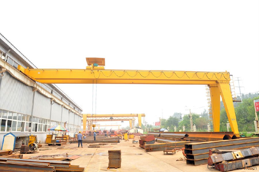
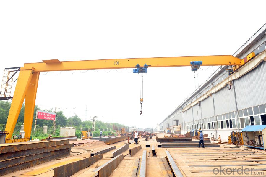
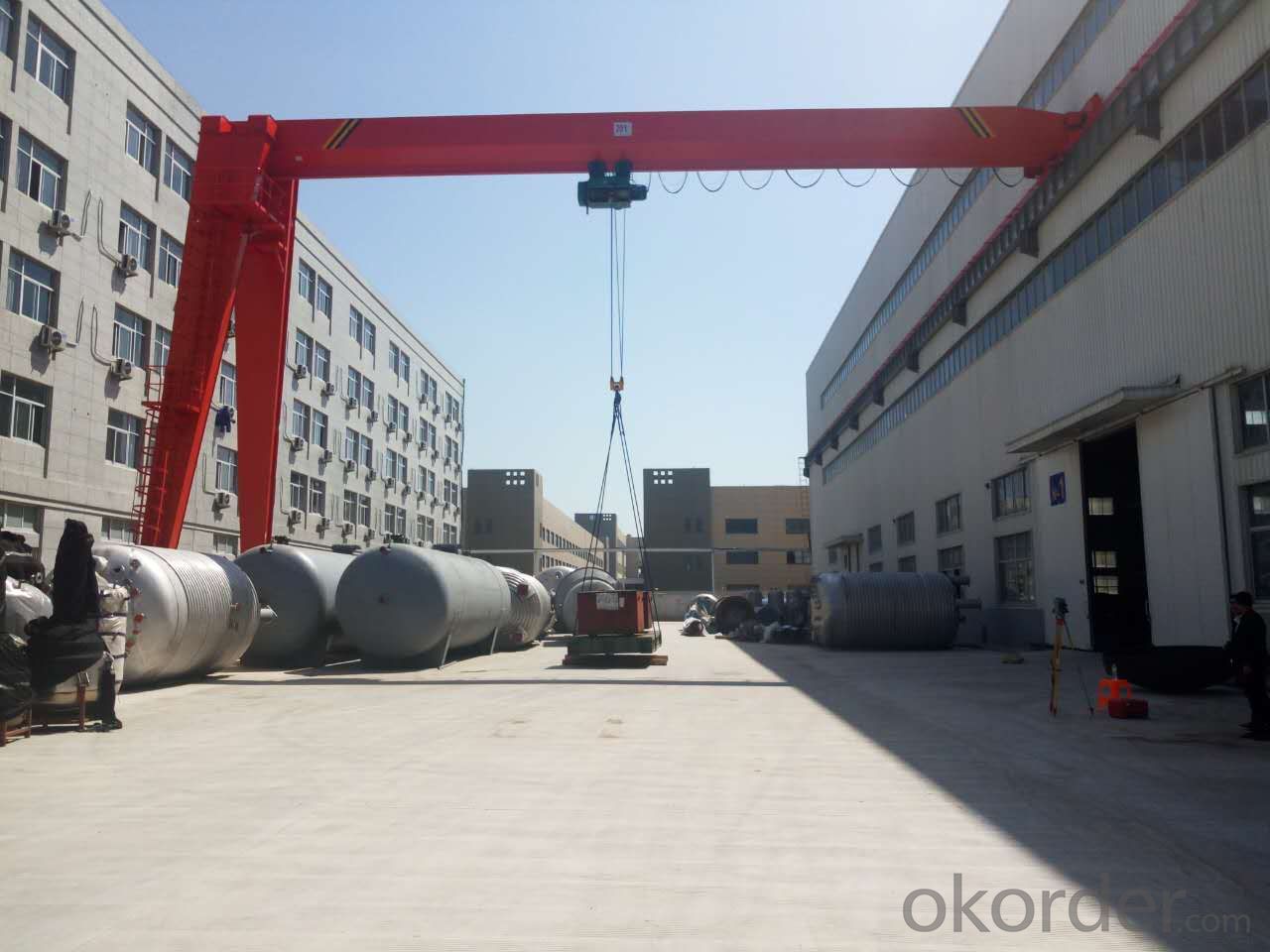
The BMH type semi-portal crane with electric hoist (hereinafter referred as crane) is designed and manufactured abiding by GB/T 3811-2008 design rules for crane and JB/T 5663-2008 gantry crane with electric hoist and other national and industrial standard design. The crane adopts CD1, MD, and other wire rope electric hoist as its lifting mechanism. It covers three-dimensional operation space by means of combing between up and down movement of the lifted hook and rear and front movement of the crane cart which can realize to move the materials and overturn operation.
Working classification of the crane applies to A3~A4, working environment temperature -25℃~+40℃, relative humidity≤85﹪。Working in no inflammable, explosive and corrosive medium conditions.
Lifting capacity :2-16t. Span:5-17m.
Sketch
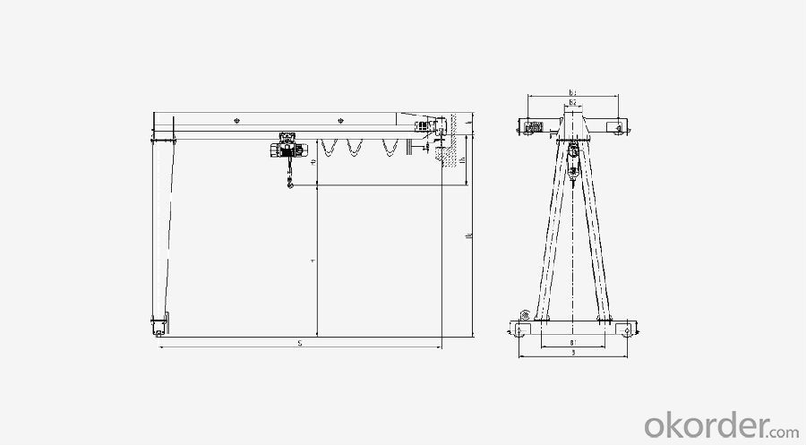
Technical specification
Lifting capacity | t | 2 | ||||||||
span | m | 5 | 11 | 14 | 17 | |||||
H0 Track Height | m | 6 | ||||||||
Travelling mechanismg
| Travelling speed | m/min | 20 / 30 | |||||||
Motor | Ordinary | kW | ZDY(D)1 21-4/0.8×2 | |||||||
Soft start | kW | YDE802 -4(D)/0.8kW×2 | ||||||||
Reducer | LDAC1 LDA1 | |||||||||
Wheel diameter | mm | φ270 | ||||||||
Electrical hoist | Type | CD1 MD1 | ||||||||
Lifting Speed | m/min | 8 0.8/8 | ||||||||
Travelling Speed | m/min | 20 / 30 | ||||||||
Motor | Lifting | kW | ZD1 31-4/3.0 ZDS1 0.4/3.0 | |||||||
Travelling | kW | ZDY112-4/0.4 | ||||||||
Working system | A4 | |||||||||
steel track recommended | P24 | |||||||||
Power source | 380V 50HZ | |||||||||
The Crane Weight | t | 2205 | 2575 | 3195 | 3780 | |||||
Max Wheel Load | KN | 17.5 | 18.9 | 20.1 | 21.7 | |||||
Basic Dimensions
| H | mm | 4920 | 4920 | 4875 | 4860 | ||||
H1 | 490 | 490 | 490 | 580 | ||||||
H2 | 1020 | |||||||||
H3 | 1080 | 1080 | 1125 | 1140 | ||||||
B | 2800 | |||||||||
B1 | 1800 | |||||||||
B2 | 400 | |||||||||
B3 | 2000 | 2000 | 2000 | 2500 | ||||||
Technical specification
Lifting capacity | t | 3 | |||||||||
span | m | 5 | 11 | 14 | 17 | ||||||
H0 Track Height | m | 6 | |||||||||
Travelling mechanismg
| Travelling speed | m/min | 20 / 30 | ||||||||
Motor | Ordinary | kW | ZDY(D)1 21-4/0.8×2 | ||||||||
Soft start | kW | YDE802 -4(D)/0.8kW×2 | |||||||||
Reducer | LDAC1 LDA1 | ||||||||||
Wheel diameter | mm | φ270 | |||||||||
Electrical hoist | Type | CD1 MD1 | |||||||||
Lifting Speed | m/min | 8 0.8/8 | |||||||||
Travelling Speed | m/min | 20 / 30 | |||||||||
Motor | Lifting | kW | ZD1 32-4/4.5 ZDS1 0.4/4.5 | ||||||||
Travelling | kW | ZDY112-4/0.4 | |||||||||
Working system | A4 | ||||||||||
steel track recommended | P24 | ||||||||||
Power source | 380V 50HZ | ||||||||||
The Crane Weight | t | 2510 | 3160 | 3590 | 4470 | ||||||
Max Wheel Load | KN | 23.2 | 24.8 | 25.9 | 28.3 | ||||||
Basic Dimensions
| H | mm | 4745 | 4745 | 4745 | 4725 | |||||
H1 | 530 | 530 | 580 | 660 | |||||||
H2 | 1135 | ||||||||||
H3 | 1255 | 1255 | 1255 | 1275 | |||||||
B | 2800 | 2700 | |||||||||
B1 | 1800 | 1700 | |||||||||
B2 | 400 | ||||||||||
B3 | 2000 | 2000 | 2000 | 2500 | |||||||
Technical specification
Lifting capacity | t | 3 | |||||||||
Span | m | 5 | 11 | 14 | 17 | ||||||
H0 Track Height | m | 6 | |||||||||
Travelling mechanismg
| Travelling speed | m/min | 20 / 30 | ||||||||
Motor | Ordinary | kW | ZDY(D)1 21-4/0.8×2 | ||||||||
Soft start | kW | YDE802 -4(D)/0.8kW×2 | |||||||||
Reducer | LDAC1 LDA1 | ||||||||||
Wheel diameter | mm | φ270 | |||||||||
Electrical hoist | Type | CD1 MD1 | |||||||||
Lifting Speed | m/min | 8 0.8/8 | |||||||||
Travelling Speed | m/min | 20 / 30 | |||||||||
Motor | Lifting | kW | ZD1 32-4/4.5 ZDS1 0.4/4.5 | ||||||||
Travelling | kW | ZDY112-4/0.4 | |||||||||
Working system | A4 | ||||||||||
steel track recommended | P24 | ||||||||||
Power source | 380V 50HZ | ||||||||||
The Crane Weight | t | 2510 | 3160 | 3590 | 4470 | ||||||
Max Wheel Load | KN | 23.2 | 24.8 | 25.9 | 28.3 | ||||||
Basic Dimensions
| H | mm | 4745 | 4745 | 4745 | 4725 | |||||
H1 | 530 | 530 | 580 | 660 | |||||||
H2 | 1135 | ||||||||||
H3 | 1255 | 1255 | 1255 | 1275 | |||||||
B | 2800 | 2700 | |||||||||
B1 | 1800 | 1700 | |||||||||
B2 | 400 | ||||||||||
B3 | 2000 | 2000 | 2000 | 2500 | |||||||
Product feature
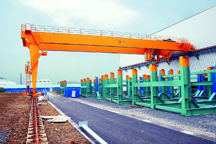
The mechanical structure of crane mainly consists of crane span structure, crane traveling mechanism, trolley traveling mechanism and lifting mechanism.
The span structure mainly consists of girder, upper beam, bottom beam, landing legs, ladder landing and other parts.
The main bearing carrier of crane with electric hoist is girder, in the meanwhile, it is the operating track of electric hoist.
The solid web girder which is made of pressed steel U-shape groove welded with joist steel, or the box girder welded with steel plates acts as girder. The deflection upward of girder should be (0.9/1000~1.4/1000)S. The upper beam and bottom beam is the basics of bearing girder and loading, in the meanwhile, it is the bond between girder and traveling mechanism. It is one of the main bearing carriers of crane metal structure. With the excellent property of light and handy structure, good rigidity, great appearance and welding technology, it is made of pressed steel U-shape groove welded with joist steel or the box girder welded with steel plates.
The landing legs consist of upper flange, bottom flange and the box shore which is assembled with steel plates. The upper flange is big and the bottom flange is small, which made the landing legs as big-end-up variable section structure. It can load vertical and horizontal loading effectively.
The girder between upper beam adopts bolt add and subtract upper flange hanging joint structure with simple structure and easy installation, which is convenient to transport and reserve.
The flanges of girder and landing legs which is symmetrically set on both sides of girder is fastened by bolts. And then, it makes the space between two landing legs narrow upper and wide bottom, which forms the space angle as A type. It improves the stability of crane. The landing leg and bottom beam is connected with bolt.
The traveling mechanism of crane consists of running motor, running gear reduction, wheel parts and other parts.
The traveling mechanism of crane adopts soft start motor. The motor comes with brake with a reliable braking performance. The motor is mounted above the bottom beam, which can save space. It adopts separate drive methods. It adopts three-in-one gear reduction and open gear drive type with a small width and no coupling.
The lifting mechanism mainly consists of coiling block, shell of coiling block, lifting motor, lifting gear reduction, wire rope, hook group load lifting limiter and others.
Technical specification
Lifting capacity | t | 3 | |||||||||
span | m | 5 | 11 | 14 | 17 | ||||||
H0 Track Height | m | 6 | |||||||||
Travelling mechanismg
| Travelling speed | m/min | 20 / 30 | ||||||||
Motor | Ordinary | kW | ZDY(D)1 21-4/0.8×2 | ||||||||
Soft start | kW | YDE802 -4(D)/0.8kW×2 | |||||||||
Reducer | LDAC1 LDA1 | ||||||||||
Wheel diameter | mm | φ270 | |||||||||
Electrical hoist | Type | CD1 MD1 | |||||||||
Lifting Speed | m/min | 8 0.8/8 | |||||||||
Travelling Speed | m/min | 20 / 30 | |||||||||
Motor | Lifting | kW | ZD1 32-4/4.5 ZDS1 0.4/4.5 | ||||||||
Travelling | kW | ZDY112-4/0.4 | |||||||||
Working system | A4 | ||||||||||
steel track recommended | P24 | ||||||||||
Power source | 380V 50HZ | ||||||||||
The Crane Weight | t | 2510 | 3160 | 3590 | 4470 | ||||||
Max Wheel Load | KN | 23.2 | 24.8 | 25.9 | 28.3 | ||||||
Basic Dimensions
| H | mm | 4745 | 4745 | 4745 | 4725 | |||||
H1 | 530 | 530 | 580 | 660 | |||||||
H2 | 1135 | ||||||||||
H3 | 1255 | 1255 | 1255 | 1275 | |||||||
B | 2800 | 2700 | |||||||||
B1 | 1800 | 1700 | |||||||||
B2 | 400 | ||||||||||
B3 | 2000 | 2000 | 2000 | 2500 | |||||||
Technical specification
Lifting capacity | t | 16 | |||||||||
span | m | 5 | 11 | 17 | |||||||
H0 Track Height | m | 6 | |||||||||
Traveling mechanismg
| Travelling speed | m/min | 20 / 30 | ||||||||
Motor | Ordinary | kW | ZDY(D)1 22-4/1.5×2 | ||||||||
Soft start | kW | YDE90L -4(D)/1.5kW×2 | |||||||||
Reducer | LDH LDHC | ||||||||||
Wheel diameter | mm | φ400 | |||||||||
Electrical hoist | Type | CD1 MD1 | |||||||||
Lifting Speed | m/min | 3.5 0.35/3.5 | |||||||||
Travelling Speed | m/min | 18 | |||||||||
Motor | Lifting | kW | ZD1 51-4/13 ZDS1 2.2/13 | ||||||||
Travelling | kW | ZDY121-4/0.8×2 | |||||||||
Working system | A4 | ||||||||||
steel track recommended | P38 | ||||||||||
Power source | 380V 50HZ | ||||||||||
The Crane Weight | t | 4620 | 5760 | 6520 | 8460 | ||||||
Max Wheel Load | KN | 96.9 | 99.8 | 101.6 | 107.6 | ||||||
Basic Dimensions
| H | mm | 3560 | 3560 | 3560 | 3510 | |||||
H1 | 840 | 840 | 910 | 1010 | |||||||
H2 | 2300 | ||||||||||
H3 | 2440 | 2440 | 2440 | 2490 | |||||||
B | 3100 | ||||||||||
B1 | 1800 | ||||||||||
B2 | 500 | 600 | |||||||||
B3 | 2000 | 2000 | 2000 | 2500 | |||||||
It adopts seamless steel tube as the main materials of winding drum, which can improve its service life and reduce the use cost of user. One of the end of the winding drum is connected with output shaft of gear reduction by spline. On the other end, the antifriction bearing is erected on the extension of the end cover of motor.
The shell of winding drum is made by Q235B steel plate which is coiled by professional veneer reeling machine or assembled by welded steel plate.
With reliable braking, it adopts conic rotor brake motor with quite big starting torque, which applies to frequent direct starting during off and on operation. The lifting motor contains two methods: single speed and dual speed.
Gear reduction for lifting adopts cylindrical gearing. All of the gears have been forged and been heat treatment. It adopts deep groove ball bearing. The shell of box is made of cast iron or cast steel and then assembled.
Safety factor of wire rope is greater than 4 and it preferentially adopts linear-contact wire rope. It adopts specified 6×37+1 structure pattern in GB/T8918. Strength of extension must be no less than 1570MPa. In line with the thread groove, the steel wire rope can be coiled. The fag is fastened on the winding drum by pressing plate tightly. It is convenient to replace the steel wire rope.
Lifting hook assembly unit contains two parts: 1) single wheel type with a pulley, it applies to lifting mechanism of two(2/1denawa)coiled steel wire rope. 2) double wheel type with a pulley, it applies to lifting mechanism of four(4/1denawa)coiled steel wire rope. Lifting hook group conforms to crampon GB/T1005.1~5 standards. Safety factor is greater than 5. There exists no flaw, fold, over burning and other flaws with bright and clean surface. There exists no flaw, fish eye, occluded foreign substance and other flaw that it will influence service safety. Anti-tripper gear has been equipped on the hook for preventing the steel wire rope from falling. It can insure safe reliability during the operation.
