Loading Port:China main port
Payment Terms:TT or LC
Min Order Qty:1 unit
Supply Capability:1000 unit/month
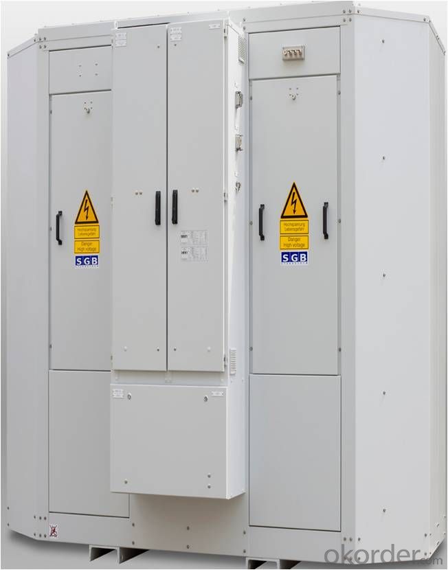
1.DESCRIPTIONOF THE JET-SYSTEMS
In this context, the SGBresin-encapsulated transformer is accommodated in a proven protective housingIP44. The cold supply air is routed directly to the housing from outside via asupply air box and a piping system. The cooling air is routed directly into thetransformer winding ducts via an air guide plate.
The exhaust air heated by thetransformer losses is blown directly into the open air via a piping system whichalso accommodates a low-noise fan and an exhaust air box.
This makes up a defined coolingsystem which can be tested in the scope of a factory test and ensures that themeasured values are also reached after installation within the wind energyplant.
No-load losses and the low loadlosses up to 30% nominal power can be dissipated without switching the fan ON. Incase of a higher load, the fan is activated via temperature sensors in thewindings.
The optimized design of the coolingsystem makes for considerable material and space savings. The targeted airsupply keeps the heating of the windings low.
The transformer has been designedfor climate class C2 and for a temperature range from + 40 to – 25°C. Temperatures between –50°C and + 50°C can be covered in exceptional cases.
In accordance with the environmentalclass E2, the transformer was tested successfully at KEMA in a climatic chamberwith moisture precipitation and a conductivity of the water of 0.5 to 1.5 S/m.If the environmental conditions exceed these requirements, the feed air box canbe equipped with appropriate filters.
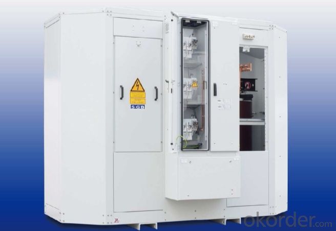
2.PERSONALAND FIRE PROTECTION
Thanks to the high reliability ofSGB resin-encapsulated transformers, the risk involved is very low. Due to thelow fire load and the fact that no coolant is used, the transformer does notcontribute essentially to fire incidents.
The dismountable housing ofgalvanized sheet steel protects the staff against touching live parts. All componentsare connected to the plant's grounding system. In case of faults, the hot gasescan escape via the ventilation and deaeration lines. Arc monitoring sensorssignal malfunctions occurring, thus allowing the plant to be switched offextremely quickly. This reduces possible risks and damage considerably. Fire gasesare also routed out of the plant via the supply and exhaust air lines, thus satisfyingthe requirements of EN 50308.
The temperatures of the windings areintegrated within the plant control system and, on being exceeded, cause theplant to be deactivated.
CONDITIONSFOR CONNECTION TO THE GRID
Wind energy plants are often builtand operated on spurs remote from the large consumption and conventional powergeneration centers. Due to the continuously rising proportion of wind energy inconsumption networks, the demands on grid operators as regards the electricalproperties are also on the increase.
Depending on the prevailing conditionsin the countries concerned, voltage fluctuations resulting from the powercharacteristics of wind parks and the behaviour in case of fault have tosatisfy different requirements. A certain amount of inductive and capacitivereactive power must be provided.
As transformers are the linkconnecting the grid to the wind generator, the conditions for connection to thepower system have a considerable effect on the transformer's design and thusthe costs of manufacturing.
Overvoltages on the transformer dueto higher mains voltage or capacitive loads, result in over-excitation and thuscause the core to heat up to inadmissibly high temperatures.
This can be compensated by areduction of induction, i.e. the enhanced use of magnetic sheet metal.
It should also be possible toprovide the rated power of the wind energy plant at undervoltage.
Thus, the transformer must beoperated continuously at approx. 10% higher current. This also means extra materialoutlay.
By optimizing the cooling of thetransformer, through ducts in the windings and the design of the magnetic core,we have managed to reduce this additional extra expense considerably.
3.TRANSPORTCONDITIONS AND VIBRATIONS
As wind energy plants are exportedin high quantities, the stress imposed by transport, especially over the lastfew meters, must be considered. We know from experience that the risks arehigher than those caused by vibration in the wind energy plant and canrealistically be compared to those caused by serious earthquakes.
Thus, the cores of SGB transformersused for wind energy plants are not only secured by gluing the core plates andbandages, but also by pins passed through the core yokes.
Moreover, clamping of theglass-fibre reinforced HV winding and the LVwinding glued with Prepreg is effected by a support system with cup springs.
4.SUMMARY
The targeted cooling within the JetSystem permits material savings and provides a proven, reliable and low-costversion of safe interfacing of wind energy plants to supply grids.
SGB-Cast ResinTransformers
leading in on- andoff-shore solutions
_ High reliability
_ Low fire load
Technical requirements:
_ Wide load variations
_ Harmonics cause additional losses
_ Repeated switching operations
_ Over voltage
_ Grid connected requirements
_ Mechanical stress at transport and during service
5.SGB XINTAI ELECTRIC’SSOLUTIONS:
_ High voltage winding glass fibre reinforced. Even most extreme and rapidload
fluctuation will not induce cracingof insulation
_ Calculation of harmonic losses. Reducing the losses by using the rightshape of
conductors
_ Layer winding with linear voltage distribution, reducing the stress causedby transit
oscillation
_ Magnetic core suitable for overexcitations up to 10% over voltage
6.CHARACTERISTICS
tested by independenttest labs:
Vibration proof IABG
Climate Class C2 KEMA
Environmental Class E2 KEMA
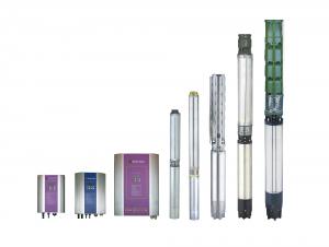
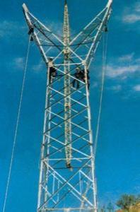
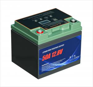
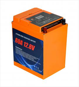
7.PICTURES