Loading Port:Tianjin
Payment Terms:TT or LC
Min Order Qty:100 m
Supply Capability:100000 m/month
Brief introdution
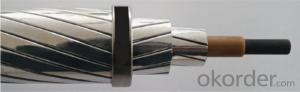
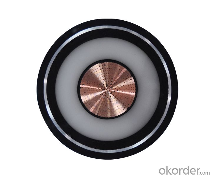
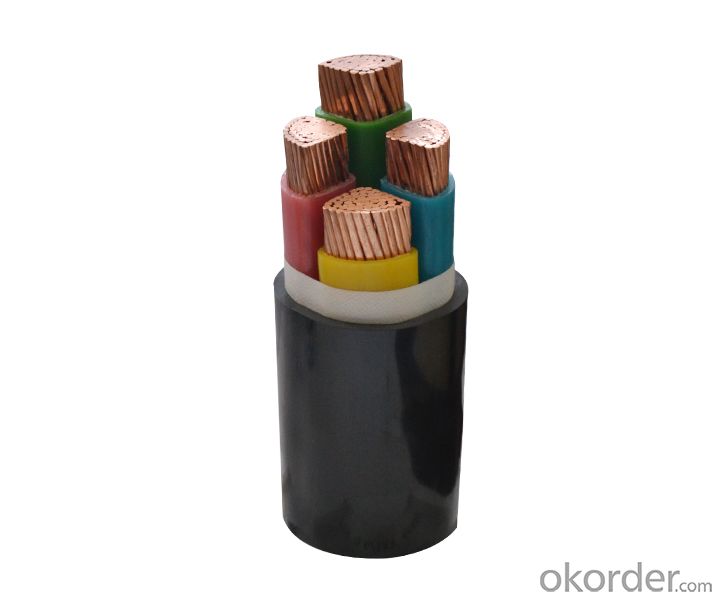
PVC insulated and sheathed control cable is suitable for connections of electric equipment in controlling monitoring loop and circuit protecting at rated voltage up to and including 450/750v (A.C.) The product has excellent characteristics not only in electric and mechanical purposes but also in chemical corrosion resistance. Heat-aging, environmental stress and flame-retardant.The product is simple in structure and convenient to use and could be laid with no restriction of different levels.
Our product of PVC insulated and sheathed control cable can be manufactured according to the standard GB 933088 which is drawn up by reference to IEC227 and IEC 502 as well as the standards of Germany, America, Japan and so on, For control cable we can also design and manufacture special control cable according to other standards or requirement of customers.
The properties of flame-retardant control cable are in accordance with the apceifications in IEC332-3, Type ZR-KVV of our control cable has been manufactured with various sizes. Welcome to choose our control cable.
Features:
Type | Designation | Main Applications |
KVV | Copper core PVC insulated and sheathed control cable | For laying indoor, tunnels, ducts, conduit etc.permanent place. |
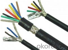
KVVP | Copper core PVC insulated and sheathed copper wire shielded control cable | For laying indoor, ducts. Conduit etc. permannet place where shield is required. |
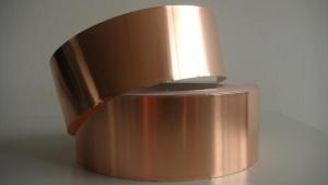
KVVP2 | Copper core PVC insulated and sheathed copper tape shielded control cable | Ditto |
KVV22 | Copper core PVC insulated and sheathed steel tape armoured control cable | For laying indoor, tunnels, ducts, conduit and direct burial etc.Pemanent place, able to bear greater mechanical force. |
KVV32 | Copper core PVC insulated and sheathed fine steel wire armoured control cable | For laying indoor, tunnels, ducts, conduit and shaft etc.permanent place, able to bear greater pulling force. |
KVVR | Copper core PVC insulated and sheathed flexible control cable. | For laying indoor and flexible required etc. place easy to move. |
KVVRP | Copper core PVC insulated and sheathed copper wire braiding shielded flexible control cable | For laying indoor, and flexible and shield required etc. place easy to move. |
ZR-KVV | Copper core PVC insulated and sheathed flame-retardant control cable. | For being applied on heat engine and heat controling appliance. |
Specification:
No. of core & Nominal cross section mm2 | Conductor Construction No./dia. mm | Norminal insulation thickness mm | Nominal sheath thickness mm | Overall Dia. mm | Weight kg/km | Resistance of conductor at 20℃ Max. Ω/km | Insulation resistance at 70℃ Min. MΩ.km | Test voltage V |
3 x 0.75A | 1/0.97 | 0.6 | 1.2 | 8.4 | 68 | 24.5 | 0.012 | 3000 |
10 x 0.75A | 1/0.97 | 0.6 | 1.2 | 12.5 | 174 | 24.5 | 0.012 | 3000 |
24 x 0.75A | 1/0.97 | 0.6 | 1.5 | 18.0 | 376 | 24.5 | 0.012 | 3000 |
48 x 0.75A | 1/0.97 | 0.6 | 1.7 | 23.0 | 689 | 24.5 | 0.012 | 3000 |
Table 1.2
No. of core & Nominal cross section mm2 | Conductor Construction No./dia. mm | Norminal insulation thickness mm | Nominal sheath thickness mm | Overall Dia. mm | Weight kg/km | Resistance of conductor at 20℃ Max. Ω/km | Insulation resistance at 70℃ Min. MΩ.km | Test voltage V |
3 x 0.75B | 7/0.37 | 0.6 | 1.2 | 8.8 | 72 | 24.5 | 0.014 | 3000 |
10 x 0.75B | 7/0.37 | 0.6 | 1.2 | 13.5 | 183 | 24.5 | 0.014 | 3000 |
24 x 0.75B | 7/0.37 | 0.6 | 1.5 | 19.0 | 396 | 24.5 | 0.014 | 3000 |
48 x 0.75B | 7/0.37 | 0.6 | 1.7 | 25.0 | 726 | 24.5 | 0.014 | 3000 |
Table1.3
No. of core & Nominal cross section mm2 | Conductor Construction No./dia. mm | Norminal insulation thickness mm | Nominal sheath thickness mm | Overall Dia. mm | Weight kg/km | Resistance of conductor at 20℃ Max. Ω/km | Insulation resistance at 70℃ Min. MΩ.km | Test voltage V |
3 x 1A | 1/1.13 | 0.6 | 1.2 | 8.8 | 79 | 18.1 | 0.011 | 3000 |
10 x 1A | 1/1.13 | 0.6 | 1.2 | 14.0 | 223 | 18.1 | 0.011 | 3000 |
24 x 1A | 1/1.13 | 0.6 | 1.5 | 19.0 | 451 | 18.1 | 0.011 | 3000 |
48 x 1A | 1/1.13 | 0.6 | 1.7 | 24.5 | 835 | 18.1 | 0.011 | 3000 |
Table 1.4
No. of core & Nominal cross section mm2 | Conductor Construction No./dia. mm | Norminal insulation thickness mm | Nominal sheath thickness mm | Overall Dia. mm | Weight kg/km | Resistance of conductor at 20℃ Max. Ω/km | Insulation resistance at 70℃ Min. MΩ.km | Test voltage V |
3 x 1B | 7/0.43 | 0.6 | 1.2 | 9.2 | 83 | 18.1 | 0.011 | 3000 |
10 x 1B | 7/0.43 | 0.6 | 1.2 | 15.0 | 235 | 18.1 | 0.013 | 3000 |
24 x 1B | 7/0.43 | 0.6 | 1.5 | 20.5 | 474 | 18.1 | 0.013 | 3000 |
48 x 1B | 7/0.43 | 0.6 | 1.7 | 26.5 | 877 | 18.1 | 0.013 | 3000 |