PV-Cable (Cable for Photovoltaic-Systems)

Loading Port:China Main Port

Payment Terms:TT OR LC

Min Order Qty:-

Supply Capability:-

Product Description:

The product based on 2PFG1169\08.2007 is applicable for flexible cables (wires) with single conductor used at the DV side of photovoltaic system with the maximum allowable DC voltage as 1.8KV (conductor-to-conductor, non-earthed system). The product is suitable for the use under Class II security level with the maximum ambient temperature for running cables up to 90c, and many cables can be co-used in parallel.


Uses: This product is applicable to shared antenna systems, closed circuit television system and other signal transmission, and such cable has the characteristics of small attenuation and strong anti-interference.

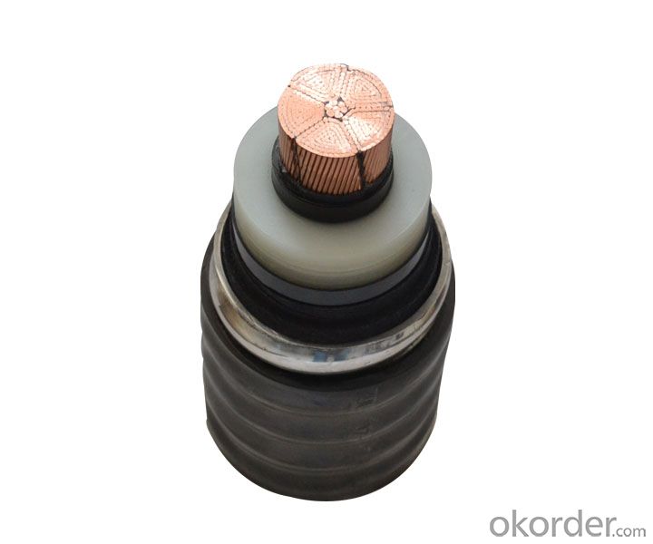
Structure and size of YWV (Y) PE physical foaming insulated coaxial RF cable products


Items
Sizes
SYWV(Y)-75-5
SYWV(Y)-75-7
SYWV(Y)-75-9
SYWV(Y)-75-12
Inner conductor diameter
1.00±0.02
1.66±0.02
2.15±0.03
2.77±0.03
Outer diameter of foaming medium (insulator)
4.80±0.20
7.25±0.20
9.00±0.25
11.50±0.30
Outer conductor
Aluminum-plastic composite belt or aluminum foil + tinned soft copper wire braiding, and the nominal diameter when the tinned copper wire is used in braid
0.12~0.15
0.12~0.15
0.12~0.18
0.12~0.20
The maximum diameter braided angle of outer conductor ≤ 45 °, filling factor of 0.23 (minimum)
5.8
8.3
10.1
12.6
Jacket
Thickness
0.70
0.85
0.96
1.00
Outer diameter
7.2±0.30
10.3±0.30
12.2±0.40
15.40±0.40
Delivery length
Length of each volume
100
100
200
200
Short break
20
50
50
50
As for length of each conducting wire of -7, -9, -12, the order requirements shall prevail

Electrical performance of SYWV (Y) polyethylene physical foaming insulated coaxial RF cable products

Items
Sizes
SYWV(Y)-75-5
SYWV(Y)-75-7
SYWV(Y)-75-9
SYWV(Y)-75-12
Core cable dielectric strength
1.6
1.6
1.6
1.6
Insulation Resistance 500V DC >
10000
10000
10000
10000
Sheath dielectric strength
Spark test
3.0
5.0
8.0
8.0
Water immersion test
2.0
3.0
5.0
5.0
Characteristic impedance 200MHZ
75±3.0
75±2.5
75±2.5
7.5±2.0
Voltage decrease constant
50MHz
4.9
3.1
2.6
2.0
200MHz
9.9
6.5
5.2
4.1
550MHz
16.8
10.7
8.5
6.7
800MHz
21.0
13.9
11.5
92
Return loss
VHF
20
20
20
23
VHF
18
18
18
20

SYV Solid polyethylene insulated RF cable:

Type
Cable structure parameters
Inner conductor
Insulation
Outer conductor
Jacket
Structure elements/diameter
Outer diameter
Structure
Nominal thickness
Thinnest thickness
Outer diamete
SYV75-2
7/0.08
1.5±0.10
Single braid layer
0.43
0.30
2.9±0.10
SYV75-3
7/0.17
3.0±0.15
Single braid layer
0.66
0.45
5.0±0.25
SYV75-5-1
1/0.72
4.6±0.20
Single braid layer
0.90
0.60
7.1±0.30
SYV75-5-2
7/0.26
4.6±0.20
Single braid layer
0.90
0.60
7.1±0.30
SYV75-7
7/0.40
7.30±0.25
Single braid layer
1.0
0.70
10.2±0.30
SYV75-9
1/1.37
9.0±0.30
Single braid layer
1.2
0.80
12.4±0.40
SYV50-2-1
7/0.15
1.5±0.10
Single braid layer
0.43
0.30
2.9±0.10
SYV50-2-2
1/0.68
2.2±0.10
Single braid layer
0.56
0.40
4.0±0.20
SYV50-3
1/0.90
3.0±0.15
Single braid layer
0.66
0.45
5.0±0.25
SYV50-5-1
1/1.37
4.6±0.20
Single braid layer
0.90
0.60
7.0±0.30
SYV50-5-2
1/1.37
4.6±0.20
Single braid layer
0.90
0.60
7.8±0.30
SYV50-7-1
7/0.76
7.3±0.25
Single braid layer
1.0
0.70
10.2±0.30
SYV50-7-2
7/0.76
7.3±0.25
Single braid layer
1.0
0.70
11.2±0.30

SYKV vertical hole PE insulated RF cable:

Structure
Type
Inner conductor
Insulation outer diameter
Insulation resistance
Characteristic impedance
Capacitance
Attenuation Coefficient
Reference Weight
50MHz
200MHz
800MHz
Vertical hole Insulation
SYKV-75-5
1/1.00
4.8
5000
75±3
60
5.3
10.8
22.9
50
SYKV-75-7
1/1.60
7.3
5000
75±3
60
3.4
7.1
15.2
95
SYKV-75-9
1/2.00
9.0
5000
75±3
60
2.8
5.7
12.5
153