Loading Port:China main port
Payment Terms:TT OR LC
Min Order Qty:1 set
Supply Capability:100 set/month
Profile
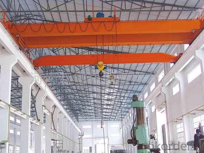
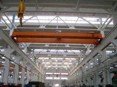
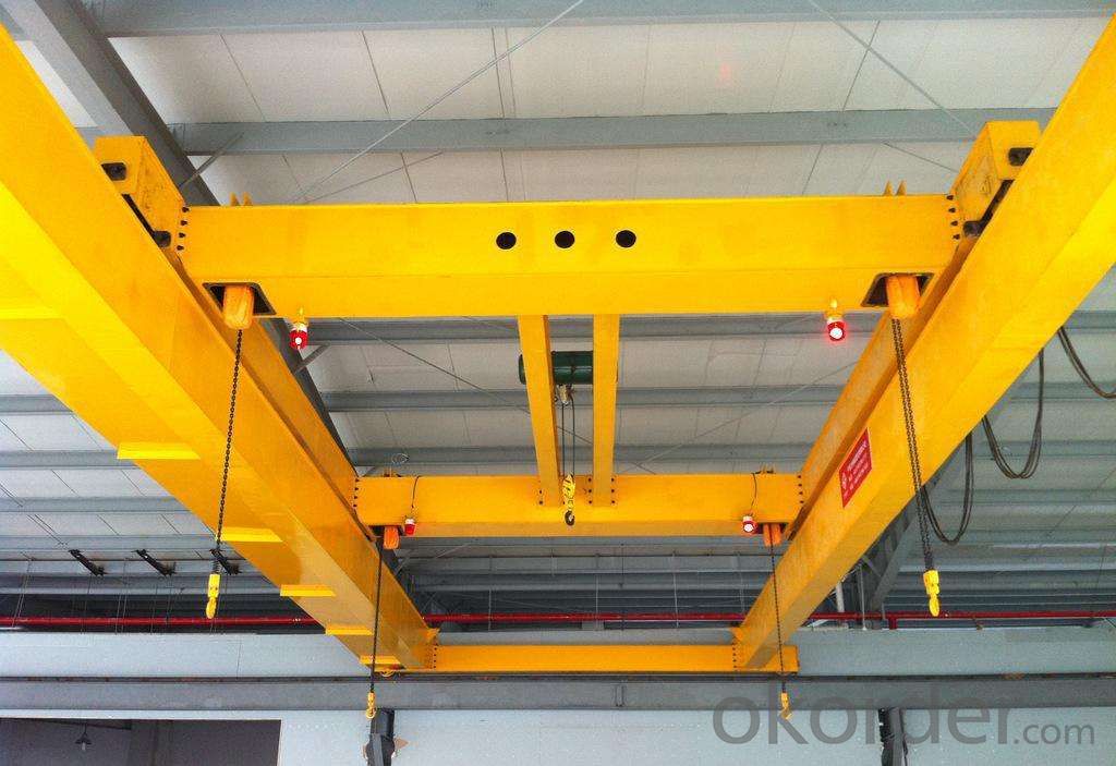
LH model electric hoist overhead crane is a handling appliance in workshop in line with GB3811-2008 and JB/T3695-2008 standard design. Lifting mechanism of the LH model electric hoist overhead crane is A2 stationary type electric hoist which includes CD1、MD1、WH164 and other types. It is widely used in machine shop, back shop of metallurgic plant, warehouse, stock plant, power station and others to transfer, assemble, maintain and handle the materials. Also can replace the general double-beam overhead crane, which is mainly used in the work shop of light textile industry and food industry. It is a kind of important tool and equipment in modern industrial enterprise, which can realize mechanization, automation during productive process, reduce heavy physical labour and raise labour productivity.
Working classification of LH model electric hoist overhead crane is A3~A4, working temperature is -20℃~+40℃. it works in non-inflammable, non-explosive and non-corrisive medium environment. Lifting capacity of the crane is 3~63t. Span is 7.5~31.5 meter. Power resource is three phase AC. Rated frequency is 50Hz or 60Hz.. Rated voltage is 220V~660V. Upper limit of admissible voltage fluctuation of electric motor and electric appliance is +10% rated voltage. Lower limit (when it is in spike voltage) is -15% rated voltage. Loss of voltage of inner crane is no more than 3%.
Ground control, remote control and control in cab can be chose in accordance with specified working condition. So as to the operation in cab, it has two operation methods, open cab and closed cab. Generally speaking, traveling speed of ground operation is 20 m/min、30 m/min. Traveling speed in cab operation is 30 m/min, 45 m/min and 60 m/min. Traveling speed of remote operation can be determined in line with actual requirement of user. It will be no more than 50m/min in principle. Traveling speed of crane can adopt frequency control type, which can satisfy demanding of different traveling speed. The user should note in the order contract when it is need.
The product has the following advantage, such as tight structure, good rigidity, convenient operation, low noise. Low headroom of building, light dead weight, reliability and safety, good appearance and etc.
The LH model electric hoist overhead crane consists of crane span structure, trolley, cart and electric control system.


Sketch

Technical specification
Lifting capacity(t) | Span S(m) | Basic parameter | Fundamental dimensions | |||||||||||
Lifting speed(m/min) | Trolley traveling speed (m/min) | Cart traveling speed(m/min) | H (mm) | H1 (mm) | H2 (mm) | S1 (mm) | S2 (mm) | b (mm) | W (mm) | K (mm) | B1 (mm) | B2 (mm) | ||
5 | 10.5 |
8 or(8/0.8) |
20 |
20 | 1318 | 40 | 114 | 1221 | 1175 | 135 | 3300 | 1400 | 260 | 580 |
13.5 | 1318 | 40 | 114 | 1221 | 1175 | 135 | 3300 | 1400 | 260 | 580 | ||||
16.5 | 1318 | 90 | 114 | 1221 | 1175 | 135 | 3300 | 1400 | 260 | 580 | ||||
19.5 | 1418 | 40 | 214 | 1221 | 1175 | 135 | 3300 | 1400 | 260 | 580 | ||||
22.5 | 1418 | 90 | 214 | 1221 | 1175 | 135 | 3300 | 1400 | 260 | 580 | ||||
25.5 | 1418 | 140 | 214 | 1221 | 1175 | 135 | 3300 | 1400 | 260 | 580 | ||||
28.5 | 1418 | 240 | 214 | 1221 | 1175 | 135 | 4000 | 1400 | 260 | 580 | ||||
31.5 | 1418 | 340 | 214 | 1221 | 1175 | 135 | 4000 | 1400 | 260 | 580 | ||||
Technical specification
Lifting capacity(t) | Span S(m) | Basic parameter | Fundamental dimensions | |||||||||||
Lifting speed(m/min) | Trolley traveling speed (m/min) | Cart traveling speed(m/min) | H (mm) | H1 (mm) | H2 (mm) | S1 (mm) | S2 (mm) | b (mm) | W (mm) | K (mm) | B1 (mm) | B2 (mm) | ||
10 | 10.5 |
7 or(7/0.7) |
20 |
20 | 1603 | 40 | 260 | 1375 | 1365 | 135 | 4000 | 2000 | 260 | 580 |
13.5 | 1603 | 40 | 260 | 1375 | 1365 | 135 | 4000 | 2000 | 260 | 580 | ||||
16.5 | 1603 | 90 | 260 | 1375 | 1365 | 135 | 4000 | 2000 | 260 | 580 | ||||
19.5 | 1503 | 290 | 160 | 1375 | 1365 | 185 | 3978 | 2000 | 260 | 580 | ||||
22.5 | 1503 | 390 | 160 | 1375 | 1365 | 185 | 3978 | 2000 | 260 | 580 | ||||
25.5 | 1603 | 390 | 260 | 1375 | 1365 | 185 | 3978 | 2000 | 260 | 580 | ||||
28.5 | 1605 | 392 | 262 | 1375 | 1365 | 185 | 4028 | 2000 | 260 | 580 | ||||
31.5 | 1605 | 492 | 262 | 1375 | 1365 | 185 | 4028 | 2000 | 260 | 580 | ||||
Main mental structural components
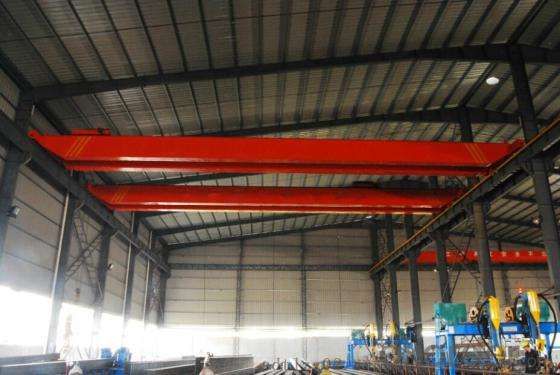
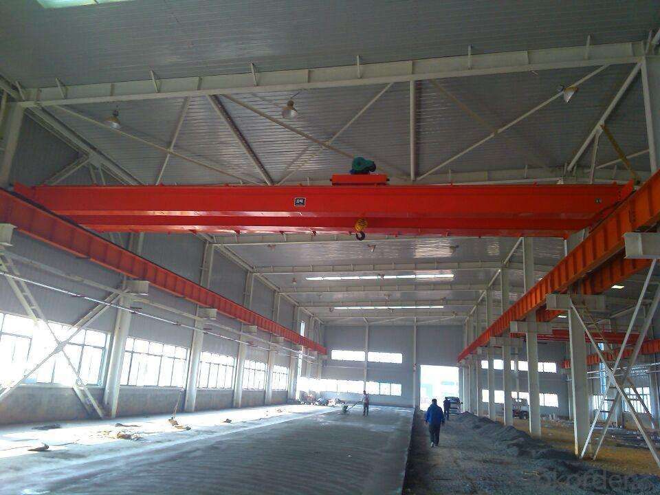
Crane span structure
The crane span structure consists of girder, end girder, walking board, conductor wire baffle, track of trolley, suspension cage for maintenance, platform, handrail and other parts. The crane span structure adopts double girder, which has the characteristic of enough strength, good rigidity and stability in the large.
The adopted materials of main structural components (girder, end girder, trolley span structure) satisfy GB/T14405-93 stipulation and meet the demanding of GB700.
Surface treatment of steel structure reached stipulated Sa21/2 in the GB8923
Girder
As the important load structure part, this kind of crane adopts bias-rail box girder. From blanking to welded into girder, each girder is manufactured on the basic of strict manufacturing technological standard in our company. The materials used to manufacture the girder adopts Q235B. After all of the steel plate have been rolled smoothly and shot blasting treatment, then it can paint weldability ground cont painting. At last, it can be in blanking. Prefabricated the deflection upward when the web is blanking. After all of the process is completed, the deflection upward must be insured as 0.9S/1000~1.4S/1000(S refer to the span of crane). The max. deflection upward value should be controlled in the range of S/10. On the main web, the total piece track is mounted for trolley traveling(The trolley adopts square steel or steel flat) . The connection among tracks are connected by welding, which can make it as one. All of the buff joint must be fitting smoothly, which can protect it traveling safely. The design of girder fully satisfy the requirement of strength, rigidity and stability.
End girder
The end girder is called as cross girder, which adopts rectangle to process completely. In this way, it can reduce the welding joints and deformation caused by assembling steel plate. The end girder locates on the end of girder, which adopts Q235B materials. The girder adopts seating-type structure, which adopts hings joint. The hand hole is set in the middle of the cross girder, which is convenient to install and detect the girder. In the both ends of end girder, it installs rubber bumper, which can avoid damage caused by crash among structural component. It has following advantage, such as simple structure, convenient installation and convenient transportation and storage. Comparing with traditional structure, the cross girder has following characteristic, light and handy structure, good rigidity, good appearance and etc.
Technical specification
Lifting capacity(t) | Span S(m) | Basic parameter | Fundamental dimensions | |||||||||||
Lifting speed(m/min) | Trolley traveling speed (m/min) | Cart traveling speed(m/min) | H (mm) | H1 (mm) | H2 (mm) | S1 (mm) | S2 (mm) | b (mm) | W (mm) | K (mm) | B1 (mm) | B2 (mm) | ||
16 | 10.5 |
3.5 or(3.5/0.35) |
20 |
20 | 1509 | 90 | -529 | 1527 | 1463 | 185 | 3928 | 2000 | 260 | 580 |
13.5 | 1509 | 140 | -529 | 1527 | 1463 | 185 | 3928 | 2000 | 260 | 580 | ||||
16.5 | 1509 | 240 | -529 | 1527 | 1463 | 185 | 3978 | 2000 | 260 | 580 | ||||
19.5 | 1609 | 240 | -429 | 1527 | 1463 | 185 | 3978 | 2000 | 260 | 580 | ||||
22.5 | 1609 | 342 | -429 | 1527 | 1463 | 185 | 3978 | 2000 | 260 | 580 | ||||
25.5 | 1609 | 442 | -429 | 1527 | 1463 | 185 | 4028 | 2000 | 260 | 580 | ||||
28.5 | 1609 | 542 | -429 | 1527 | 1463 | 185 | 4078 | 2000 | 260 | 580 | ||||
31.5 | 1709 | 542 | -329 | 1527 | 1463 | 185 | 4078 | 2000 | 260 | 580 | ||||
Technical specification
Lifting capacity(t) | Span S(m) | Basic parameter | Fundamental dimensions | |||||||||||
Lifting speed(m/min) | Trolley traveling speed (m/min) | Cart traveling speed(m/min) | H (mm) | H1 (mm) | H2 (mm) | S1 (mm) | S2 (mm) | b (mm) | W (mm) | K (mm) | B1 (mm) | B2 (mm) | ||
20 | 10.5 |
4.2 or(4.2/0.42) |
20 |
20 | 1588 | 140 | -420 | 1815 | 1655 | 185 | 3928 | 2000 | 260 | 580 |
13.5 | 1588 | 240 | -420 | 1815 | 1655 | 185 | 3978 | 2000 | 260 | 580 | ||||
16.5 | 1688 | 242 | -320 | 1815 | 1655 | 185 | 3978 | 2000 | 260 | 580 | ||||
19.5 | 1690 | 342 | -318 | 1815 | 1655 | 185 | 4028 | 2000 | 260 | 580 | ||||
22.5 | 1690 | 444 | -318 | 1815 | 1655 | 185 | 4028 | 2000 | 260 | 580 | ||||
25.5 | 1790 | 444 | -218 | 1815 | 1655 | 185 | 3978 | 2000 | 310 | 630 | ||||
28.5 | 1890 | 444 | -118 | 1815 | 1655 | 185 | 3978 | 2000 | 310 | 630 | ||||
31.5 | 1890 | 544 | -118 | 1815 | 1655 | 185 | 4028 | 2000 | 310 | 630 | ||||
Attachment
In line with GB6067-85 relative regulation about handrail and requirement of user, the height of safe handrail is no less than 1000mm with no less than 100mm siding height is set on the walking board of the crane. And then, it is mounted with horizontal cross bar. Anywhere on the handrail can load 1KN. Anywhere on the handrail will not deform where it loads 1KN from any directions.
In order to safely maintain the crane conductor wire device, on the one end of crane span structure is set power source sliding wire guard plate and maintaining suspension cage. On the suspension cage, it is mounted with current collector support frame baseboard. On the crane span structure, the width between ladder and access is no less than 500mm and set with handrail and guard plate. The tread of ladder adopts checkered plate, which has the function of skid resistance. It should adopts vertical ladder when it is controlled in the cab on the crane, which can reduce the width of whole machine.
Trolley span structure
The material of main structure component of the trolley span structure adopts Q235B. The trolley span structure adopts six-girder structure, which consists of two end girders, two carlines and two cross girders. The whole trolley span structure is welded by section with simple structure and good appearance. The end girder and carline are connected by high strength bolts, which can avoid one wheel suspended phenomenon of trolley caused by stiff problem. Its natural bow trolley is S/2000(s refers to trolley span of trolley) under the loading of rated capacity, which insure its stable traveling mechanism with enough strength and rigidity.
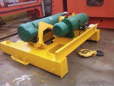
Lifting mechanism
The lifting mechanism adopts A2 fixed high-quality steel-wire rope electric hoist which includes the type of CD,MD or WH. The electric hoist consists of electric motor, reducer, winding drum, hook groups, pulley block and other parts.
Traveling mechanism
Traveling mechanism adopts three-in-one gear motor to separately drive. This kind of drive method has the function of stable traveling, light weight, good university, convenient installation and maintenance. The traveling performance will not be influenced by deformation when it is lifting.