Loading Port:China main port
Payment Terms:TT OR LC
Min Order Qty:1 set
Supply Capability:10 set/month
Profile
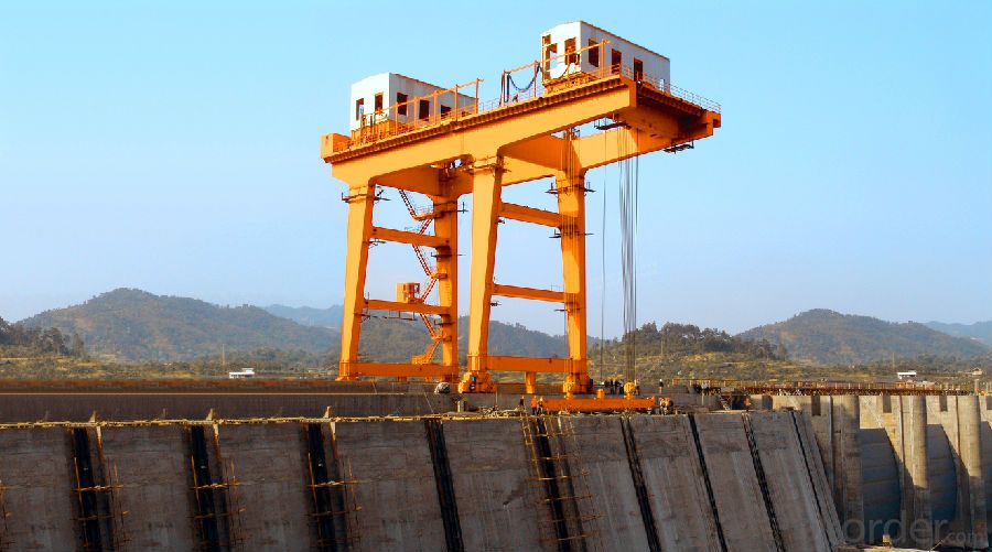
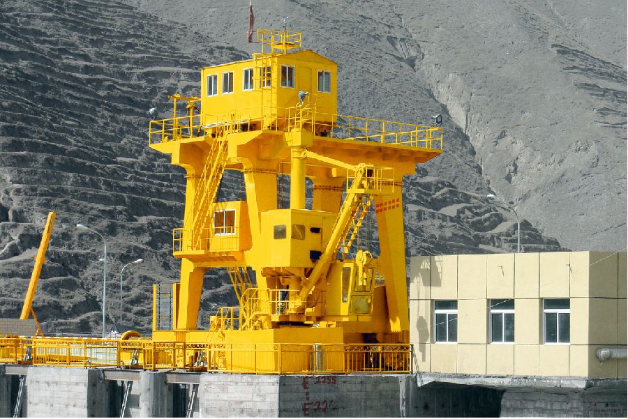
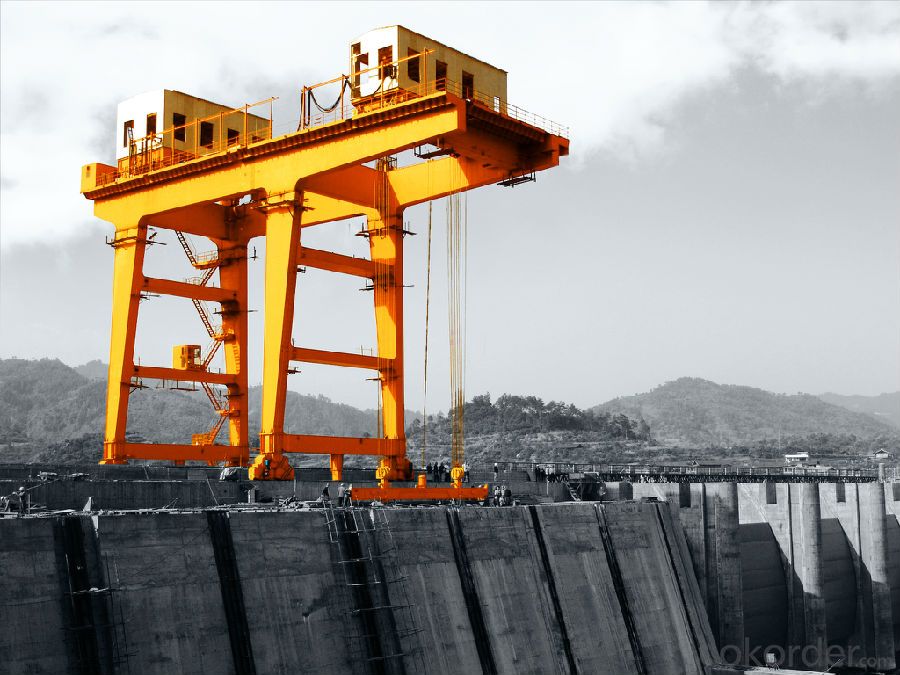
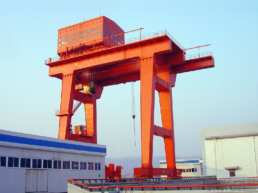
The Headstock Gear used for power station gate opening and closing, trash rack cleaning, trash rack and hoist lifting, water inlet maintenance gate opening and lifting, intake gate hydraulic hoist accidents, the installation and maintenance of hoist crane.
Main structural features
The Headstock Gear is mainly composed of lifting mechanism, operation mechanism, safety device, frame, electrical equipment and so on.
Lifting Mechanism
- The lifting mechanism is composed of pulley block, drum group, driving device (including open gear pair, reducer, brake, motor, etc.) and safety devices.
- The Headstock Gear is connected with the gate and the slings on the movable pulley, for make the gate is opened and closed
-The hoisting mechanism of the Headstock Gear is double lifting point, and the lifting mechanism which two drum and two drive device is adopted. The speed of two drums and two moving pulley groups are consistent.
-The two sets of hoisting mechanism is connected by rigid synchronous shaft, and the rigid synchronous shaft is connected by detachable coupling.
-If the hoisting device is equipped with a normally closed brake, the safety factor of the brake is not less than 1.75.
-If the lifting device is equipped with two normally closed brakes, the safety factor of the brake is not less than 1.25.
-The lifting and decelerating device is composed of a standard reducer and an open gear drive, the transmission ratio of the open gear pair is less than 6.3.
Travelling Mechanism
-The travelling mechanism is composed of motor, coupling, brake, transmission shaft, reducer, wheel set and so on.
-The travelling mechanism of trolley adopts centralized driving, and the travelling mechanism of cart is driven separately.
-Full closed drive is used between the each motor and the wheel group in the travelling mechanism of trolley.
-The wheel diameter and material selected according to the most unfavorable conditions to ensure the wheel overload phenomenon will not occur.
-The travelling mechanism is equipped with a windproof rail clamping device or a windproof anchor device.
Technical Parameters
-QPJ Model Winch Headstoke Gear
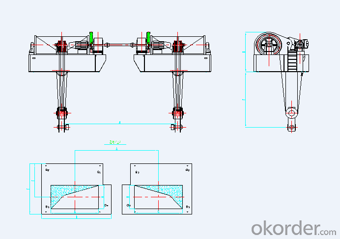
Lifting Capacity | KN | 2×1600 | 2×4000 | 2×4500 | 5000 | |
Lifting Speed | m/min | 1.73 | 1.75 | 3.28 | 2.5 | |
Lifting Height | m | 28 | 27 | 57 | 127 | |
Working Class | Q2 | |||||
Main Size | A | m | 10.4 | 4.5 | 8.3 | / |
B | 2.583 | 4.134 | 4.34 | 4.95 | ||
C | 3.2 | 4.7 | 4.5 | 4.5 | ||
D | 4.285 | 5.42 | 6.1 | 8.8 | ||
E | 3.34 | 6.3 | 6.5 | 6.6 | ||
F | 2.202 | 4.144 | 4.126 | 3.95 | ||
G | 3.1 | 3.5 | 3.5 | 4.8 | ||
H | 1.2 | 2.2 | 2.2 | 1.9 | ||
Weight | t | 54 | 153 | 192 | 138 | |
Power Supply | 3-Phases AC 50Hz 10KV | |||||
-One Way Gantry Headstoke Gear
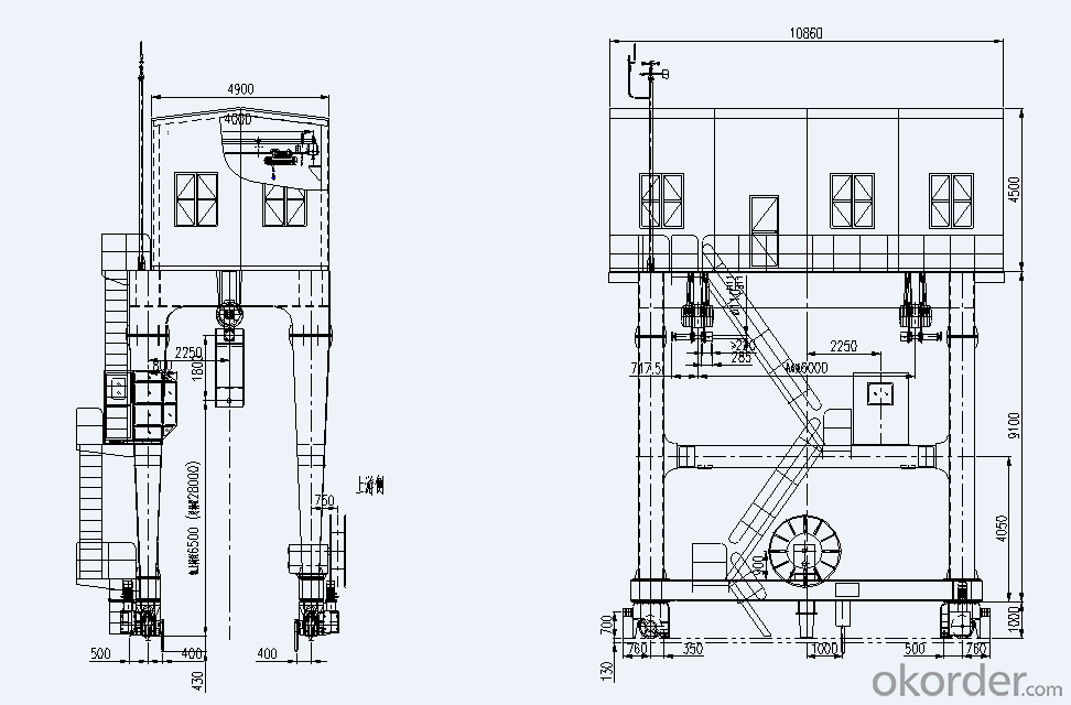
Lifting Capacity | kN | 630 | |
Span | m | 4.5 | |
Lifting Height | m | 28(Lower Track 21.5m) | |
Working Class | Q3-Mid | ||
Speed | Main Hoisting | m/min | 1.57 |
Cart Travelling | 19.4 | ||
Total Power Capacity | kW | 64 | |
Steel Track | QU80 | ||
Max. Wheel Pressure | kN | 577 | |
Power Supply | 3-Phases AC 380V 50Hz | ||
Frame and Track
-The main force material is Q235B (or Q345B). The main beam section adopts finite element method to analyze and calculate, ensure that it has sufficient strength, stiffness and overall stability.
-The vertical deflection of the middle span of Headstock Gear’s main beam is less than or equal to L/800 (L-Span length of the Headstock Gear).
-All steel plates did ball blasting pretreatment, and the standard is Sa2.5.
-Each unit of the frame is connected by high strength bolts, positioned by reaming bolts, and positioning marks are made when leaving the factory.
-Track adopts light rail or crane special track.
-Rail fixed plate along the track length spacing is less than or equal to 500mm, and adopts the symmetrical arrangement.
Safety Protection Device
-Overload limiter
When the load reaches the rated lifting weight of 90%, prompting the alarm signal.
Delay alarm when load is up to 105% (adjustable) of rated load.
When the load is up to 110% of the rated weight, the lifting power supply can be automatically cut off immediately, and the warning signal can be sent out.
-Travel limiter
Independent upper and lower limit position limiters are set on the main and auxiliary hoisting mechanisms.
The cart and trolley travelling mechanism installed travel limiter.
Rail Clamping Device and Anchor Device
The wind rail clamping device is installed on the cart and trolley.
The anchoring device is installed in the proper position where is the travelling distance of cart and the trolley. The power supply connected before it travelling and after the anchor of gantry relieve.
-Buffer
A buffer is used to cushion the inertia kinetic energy of crane running brake.
The stop position is installed at the limit position of each travelling mechanism of the crane to prevent the crane travelling over the extreme position to a dangerous level.
-Height Indicator
The hoisting mechanism set digital display instrument height indicator, it equipped with local display device which can define 4 stroke limit contact, and 4 ~ 20mA analog output.
-Anemoscope
Anemoscope is installed on the upper part of the gantry, when the wind speed exceeds the set speed, the anemoscope alarmed automatically, and the travelling mechanism of system automatically power-off.
-Other Safety Devices
A rail sweeping device is installed on the Headstock Gear, it used to clean sweep, orbit debris, preventing derailment risk.
A removable protective cover is required for the rotating parts which are dangerous to people.
The platform, walkway and escalator are designed according to the national safety regulations and standards to facilitate the maintenance and inspection of the operators.
The stair step, outdoor platform and walking table should be antiskid, the width of walking platform, platform and ladder is not less than 500mm, and the tread plate is used in walking table.
Setting emergency stop button in the proper position of rack and engine room to ensure the safety of equipment and personnel.
Setting bell and buzzer, the content should be warning the relevant personnel caution before the gantry is started.
Automatic Grabbing Beam
-The automatic grabbing beam is composed of beam body, hanging hook device, supporting guiding device, positioning device and other components.
-Each automatic grabbing beam is designed according to the load of the lifting lug under 1.1 times of the corresponding grabbing beam.
-The maximum vertical deflection of the beam is less than L/1000 (L for hanging point spacing)
Sewage Cleaning Device
-The sewage cleaning device is composed of harrow, turnover plate, hydraulic cylinder, hydraulic driving device and a guiding device.
-The turning plate is operated by the hydraulic cylinder, so as to unload the dirt on the automobile.
-Materials such as rake and turnover plate are made of hot dip galvanized steel. The rake tip uses more than 300HB wear resistant material.
-When the grab at full load, the maximum vertical deflection is less than L/800 (L for hanging point spacing).
-All mechanical, sensor, electrical components and other equipment have good waterproof performance.
-No concrete support surface between the rack and grab rails, reasonable design of grab, when the grab move between the rack and rails, the waste leaked from the grab was reduced to a minimum. The closing force of the cleaning device grab bucket is enough and safe and reliable.
