Loading Port:Shekou
Payment Terms:TT OR LC
Min Order Qty:1 kg
Supply Capability:1620 kg/month
DC reactor, also known as smoothing reactor, is mainly used on the DC side of
converter and is widely used in general frequency converter. There is a DC
current with AC component flowing through the reactor. The main purpose is to
limit the AC component superimposed on the DC current to a specified value,
keep the rectifier current continuous, reduce the current ripple value, improve
the input power factor, and suppress the harmonic generated by the converter.
effect
DC reactors are connected in series on each pole of the converter station. The
inductance is about 0.4 ~ 1.0h. Its main functions are as follows:
(1) Prevent inverter commutation failure.
(2) Reduce voltage and current harmonics in DC lines.
(3) Reduce ripple coefficient.
(4) Limit the current in the rectifier when the line is short circuited.
However, it should be noted that the value of inductance must ensure that the
DC circuit does not resonate at power frequency.
DC reactor can increase the power factor to more than 0.9. Because of its small
size, many frequency converters have installed DC reactors directly in the
frequency converter. In addition to improving the power factor, the DC reactor
can also weaken the impact at the moment when the power supply is just
connected. If AC reactor and DC reactor are equipped at the same time, the
power factor of variable frequency speed regulation system can be increased to
more than 0.95.
Structural design
The DC smoothing reactor is used for the filter circuit at the output side of
the rectifier circuit. Because there is a DC current component, the magnetic
flux of the iron core works in the first quadrant, resulting in magnetic bias.
In order to increase the inductance and prevent magnetic flux saturation, DC
smoothing reactors adopt cut iron core and add air gap to lengthen their
hysteresis loop laterally, which is a bit like the case of single ended flyback
transformer in principle. In this way, when there is a current of the same
size, B is small and not easy to be saturated.
Four factors should be considered in the structural design of open core
reactor:
1) The DC component I of the current flowing through the reactor, that is, the
average value of the inductive current IL, determines the cross-sectional area
of the winding conductor and the heating of the winding.
2) The peak to peak value of AC current component is expressed by △ IPP or
abbreviated as △ I, which is determined by the continuity requirements of
inductive current. Generally, without affecting the output voltage ripple,
twice the minimum load current ilmin output by the rectifier filter circuit is
the peak to peak of the required filter inductance current change. Thus: △ IPP
= 2ilmin
3) The inductance L required by the filter circuit is determined by the
frequency of AC current component and peak to peak △ IPP. It is an
intermediate calculated value in the process of reactor structure design,
rather than the primary factor to be considered in advance.
4) Power loss and temperature rise are factors that need to be considered in
advance in the process of reactor structure design.
There are more than one method to design DC smoothing reactor, and these
methods are unified with each other. A simple, clear and practical engineering
design method is introduced here. Its steps are as follows:
(1) Calculated energy storage
We know that if the inductance of the reactor is l and the current is I, the
stored energy is
W=1/2LI
Because the highest flux density BM is determined by the maximum current in the
reactor, I in the formula should be calculated according to the maximum
current. If the DC current is I, the peak to peak value of AC current is △
IPP.
(2) Select the material of iron core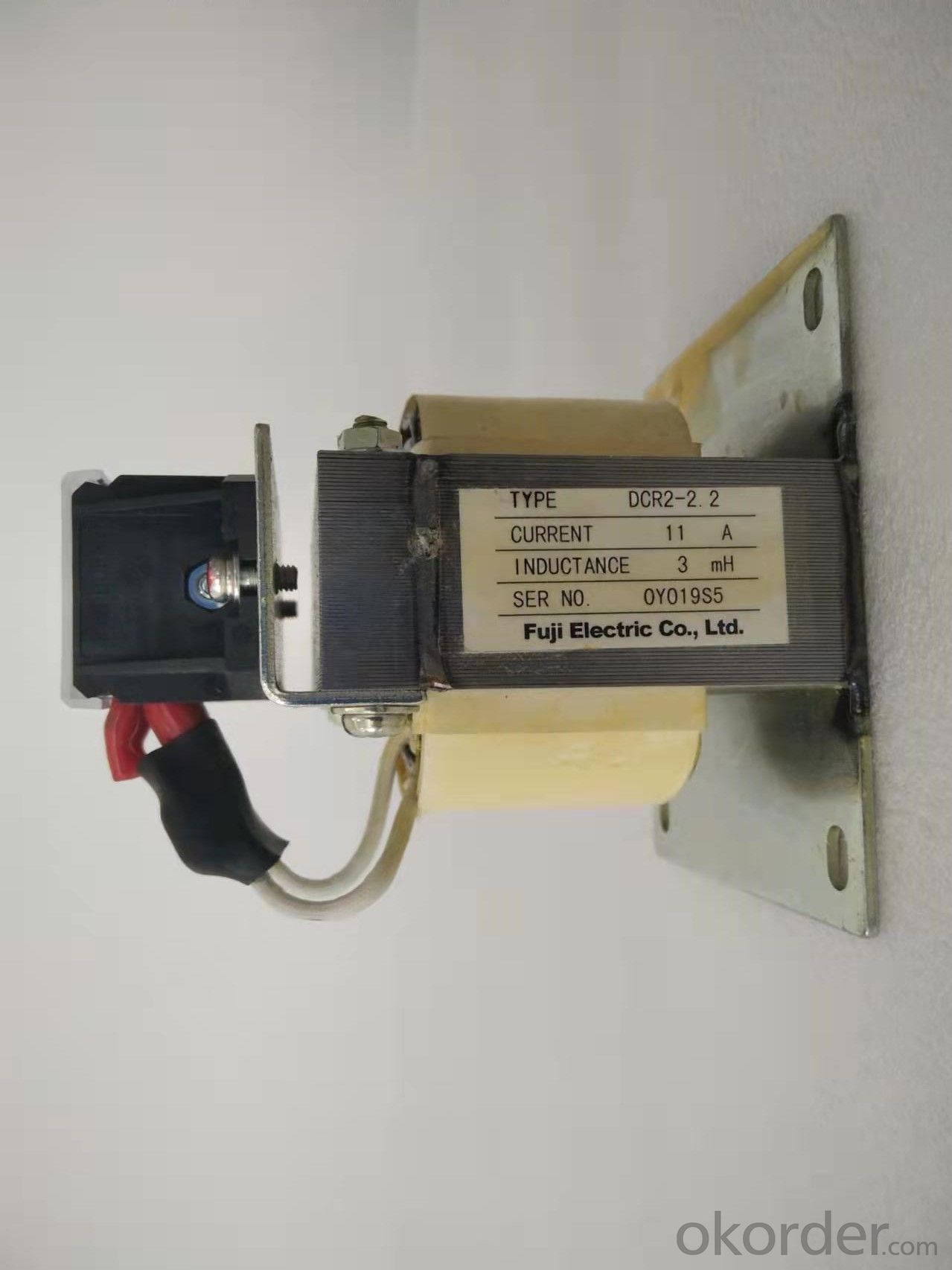
According to the proportion of AC component △ I in I, the frequency of AC
component and the index requirements of inverter on its output noise, the
material of reactor core can be selected. After the material is selected, the
maximum flux density BM and the effective coefficient K of iron core section
can be determined. Note that when selecting BM, it is generally required to
leave a large margin, because the reactor is not saturated after half an
inverter cycle of output short circuit (i.e. a normal rectifier cycle), so as
to make the protection circuit act, so as to improve the working reliability of
the inverter circuit.
(3) Select the shape of the iron core and determine the window utilization
coefficient KC
According to the material, winding process and installation structure of the
selected iron core, the shape of the iron core is selected, and then the type
of conductor is selected according to the current level to determine the window
utilization coefficient KC.
(4) Select conductor current density coefficient kJ and current density J
According to the heat dissipation conditions, the required copper consumption,
the shape of the iron core and the allowable temperature rise of the wire
package, select the appropriate current density coefficient kJ (refer to table
4.2) and the current density J of the conductor.
(5) Calculate the cross-sectional area of the wire and select the wire
The cross-sectional area of the conductor is calculated by the following
formula: S = I / J; Then select the shape and size of the wire.
(6) Calculate the number of winding turns
When calculating the number of turns of reactor winding, we should consider
making full use of the window area of iron core, so as to maximize the number
of turns and leave a certain margin for BM. N=A·Kc/S
