Loading Port:China main port
Payment Terms:TT or LC
Min Order Qty:1 unit
Supply Capability:100 unit/month
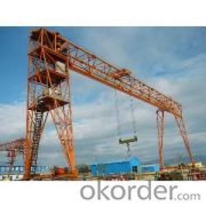
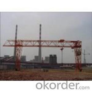
l Overview
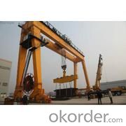
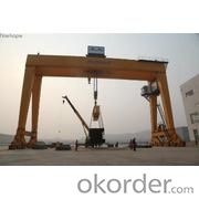
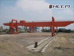
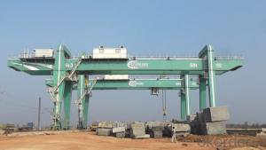
FHMG400/75-33A4 gantry crane is our large-scale product specially designed for outdoor lifting and moving large transformer. The main structure of the product adopts box frame construction, double-girder and single trolley with the M.H. rated lifting capacity of 400t, A.H. rated lifting capacity of 75t and span of 33m.
The gantry crane mainly comprised of main girder, supporting leg, lower beam, grade one connection beam, grade two connection beam, travelling bogie, trolley, platform railing and electrical control system. The main steel structure, like main girder, supporting leg and lower beam, is connected by flange, which will quicken and facilitate equipment assembly and adapt to long and short distance transportation.
l 1. Lifting Mechanism
Lifting mechanism is comprised of motor, gearbox, brake, coupling and drum. Motor and gearbox adopt world famous band product. Coupling is the new model elastic coupling of plum blossom with excellent buffing and vibration absorption and long-term service life. Brake is the new model electric-hydraulic pusher brake with reliable performance and low trouble rate.
Lifting mechanism adopts wire rope drum construction and lifting motor adopts variable-frequency motor which is managed by variable-frequency and speed regulation control system.
Lifting mechanism is equipped with reliable brake system and dead space limit device. Electric brake comes first and mechanical brake comes second. The layout of trolley mechanism is presented in the following diagram1-1.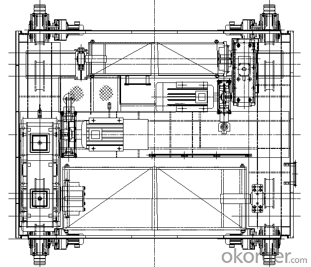
Diagram 1-1 Trolley Mechanism Layout Diagram
l 2. Trolley Travelling Mechanism
Trolley travelling mechanism adopts the same structure to realize exchange and separate drive. All of the drive, brake and transmission adopt Germany SEW “three-in-one” drive unit comprised of gearbox with hard toothed surface and brake motor. At the end, polyurethane buffer is equipped. In addition, variable-frequency and speed regulation control system is adopted for realizing fine performance, high reliability and smooth travelling.
The structure of the trolley travelling mechanism is shown by the following diagram 1-2.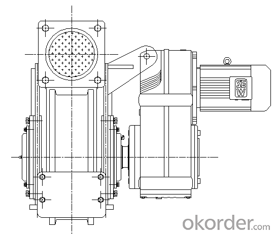
Diagram 1-2 Trolley Travelling Mechanism
l 3. Crane Travelling Mechanism
The drive of crane travelling mechanism adopts “three-in-one” drive unit comprised of gearbox, variable-frequency motor and electromagnetic brake, which is compact in structure, small in cubage and convenient in assembly and maintenance. In addition, polyurethane buffer is applied.
At the end face of bogie along the both sides of rail, “three-in-one” new model rail clamp is equipped, which integrates rail sweeping, clamping and buffering into one unit. Meanwhile, the rail clamp is equipped with stroke switch to achieve electric interlock of crane travelling mechanism.
The alarm light is equipped on crane travelling bogie for sending alarm notice during crane operation.
l 4. Structure Portion
The main structure of FHMG400/75-33A4 gantry crane is made up of main girder and double rigid legs, both of which adopt plate beam structure, high strength bolt in connection and advanced finite element structure design software in calculation.
l 5. Electrical Portion
The electrical portion of FHMG400/75-33A4 gantry crane is mainly comprised of electric station, cabinet, stroke limit for each mechanism, cable reel, overload limit and connecting cable. Electric station inside is equipped with power supply/PLC control panel, main lifting control panel, auxiliary lifting control panel, crane travelling control panel and trolley travelling control panel. Cabinet inside is equipped with operation console, overload protection display screen, touch screen, operation and monitoring facility.