Loading Port:China Main Port
Payment Terms:TT or LC
Min Order Qty:20 PCS pc
Supply Capability:1000 Ton Per Month pc/month
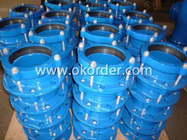
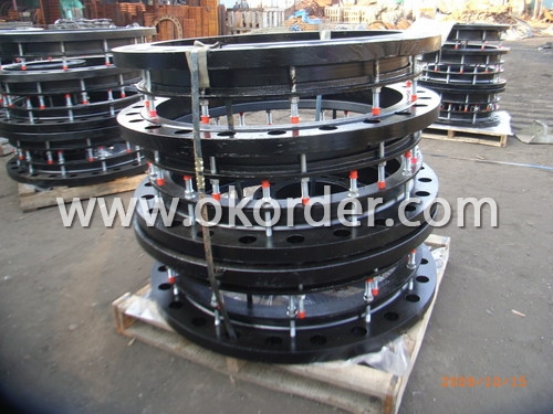
Product Introduction & Specifications of Ductile Iron Flange Adaptor
Flanged Adaptors are designed for pipelines, As a wide tolerance system.
It will fit most standard pipe materials and therefore dramatically reducesthe number of dedicated Flanged Adaptors which need to be stocked for maintenance purposes.
It is suitable for steel, GRP, PVC, PE, Ductile Iron, Cast Ironand Asbestors Cement.
When connecting PE pipes, It is important that pipe inserts are fitted to the PE pipes.
Body
DN50-DN300: Ductile Iron ASTM A536 65-45-12/GGG40/BS2789 450-12
DN350-DN600: Cast Steel
Gasket:
EPDM: for potable water
NBR: for natural gas, petroleum products, oil and compressed air.
Coating: Fusion bonded epoxy, thickness 250um up.
Fasteners:
T bolt with nut and washer.
Bolt to EN20898-1 Grade 8.8 with dachromate coating with thread protect cap.
Stainless steel fastener can be supplied upon request.
Pressure Rating: PN10/16
Fluid Temperature: 0°-50°C, excluding frost
Dimensions of Ductile Iron Flange Adaptor
|
SIZES |
RANGE |
U.WGT |
BOLT SIZE |
BOLT |
|
kgs |
QTY | |||
|
DN40 |
48-60 |
3.00 |
M12 X 115 |
2 |
|
DN50 |
59-72 |
3.30 |
M12 X 115 |
2 |
|
DN65 |
72-85 |
3.80 |
M12 X 115 |
2 |
|
DN80 |
88-103 |
4.80 |
M12 X 115 |
4 |
|
DN100 |
105-122 |
4.90 |
M12 X 115 |
4 |
|
DN100 |
109-128 |
4.90 |
M12 X 115 |
4 |
|
DN125 |
125-140 |
5.50 |
M12 X 115 |
4 |
|
DN125 |
132-146 |
6.75 |
M12 X 115 |
4 |
|
DN125 |
138-153 |
6.75 |
M12 X 115 |
4 |
|
DN150 |
155-175 |
7.50 |
M12 X 115 |
4 |
|
DN150 |
159-182 |
7.55 |
M12 X 115 |
4 |
|
DN175 |
192-210 |
9.60 |
M12 X 115 |
4 |
|
DN200 |
218-235 |
8.70 |
M12 X 115 |
4 |
|
DN225 |
230-247 |
11.80 |
M12 X 115 |
6 |
|
DN225 |
250-267 |
13.50 |
M12 X 115 |
6 |
|
DN250 |
265-280 |
13.90 |
M12 X 115 |
6 |
|
DN250 |
272-289 |
13.60 |
M12 X 120 |
6 |
|
DN300 |
315-332 |
15.00 |
M12 X 135 |
6 |
|
DN300 |
322-339 |
15.50 |
M12 X 135 |
6 |
|
DN300 |
332-349 |
16.60 |
M12 X 135 |
6 |
|
DN350 |
340-360 |
40.00 |
M14 X 160 |
8 |
|
DN350 |
351-368 |
36.00 |
M14 X 160 |
8 |
|
DN350 |
374-391 |
36.00 |
M14 X 160 |
8 |
|
DN400 |
394-412 |
36.00 |
M14 X 160 |
8 |
|
DN400 |
400-429 |
36.00 |
M14 X 160 |
8 |
|
DN400 |
410-436 |
36.00 |
M14 X 160 |
8 |
|
DN400 |
425-442 |
38.00 |
M14 X 160 |
8 |
|
DN450 |
455-472 |
48.00 |
M14 X 160 |
8 |
|
DN450 |
476-493 |
46.00 |
M14 X 160 |
8 |
|
DN450 |
480-500 |
46.00 |
M14 X 160 |
10 |
|
DN500 |
500-535 |
49.00 |
M14 X 160 |
10 |
|
DN500 |
526-546 |
49.00 |
M14 X 160 |
10 |
|
DN500 |
555-572 |
55.00 |
M14 X 160 |
10 |
|
DN600 |
566-583 |
55.00 |
M14 X 160 |
10 |
|
DN600 |
582-599 |
55.00 |
M14 X 160 |
10 |
|
DN600 |
600-635 |
58.00 |
M14 X 160 |
10 |
|
DN600 |
630-650 |
58.00 |
M14 X 160 |
10 |
|
DN600 |
645-662 |
66.00 |
M14 X 160 |
10 |
|
DN600 |
662-679 |
66.00 |
M14 X 160 |
10 |
Packing and Installation Instructions of Ductile Iron Flange Adaptor
1. Examine the pipe ends and ensure they are round, smooth, free from bulges, dents and score marks and within the outside diameter range given on the adaptor label. Weld beads mustbe ground flush maintaining correct surface profile. Ensure that pipe ends are free from scale rust or any loose debris or other surface defect that may affect coupling performance.
2. Check grade of gasket is suitable for conveyed medium.
3. If the adaptor has T bolts between the main flange body and end ring ensure that their heads are correctly located in the recesses in the back flange face.
4. Place the adaptor onto pipe end. Adjust the setting gap between pipe end and adaptor as necessary. Ensure that the pipe end is concentric with the bore of the mating flange.
5. Fit flange gasket and ensure it is concentric with the flange connecting bolts, procedures. Bolt the adaptor to the mating flange using standard bolting.
6. Tighten diametrically opposed T bolts/studs giving the nuts one or two turns at a time to thoroughtly draw up the end ring evenly. The nuts must be tightened, working around the flange adaptor as many times as necessary. On completion, radial gap between pipe and flange adaptor end ring should be even all the way round. Rubber may be seen to extrude into the gap.
Usage and Strict Quality Control of Ductile Iron Flanged Adaptor
We regards quality as an essential and integral part of our business success. To meet this, we have achieved all types of world-known certificates, making our brand products has evolved as a mark of quality!
An independent Quality Control is supervised directly by General Manager and responsible for following duties:
All inspections on raw material, semi-finished and finished products.
Tensile Strength, Hardness, Elongation and other Physical analysis.
Chemical Composition Analysis.
Dimension measurement, Visual, Conformation to standards.
Water Pressure Test.
Identifying, Recording and Disposing of rejected material.
Other Tests.
All of our manufacturing processes are strictly under control based on ISO 9001: 2008 Quality Management System.


If you have other question, please feel free to contact us at any time.