Loading Port:Shanghai
Payment Terms:TT OR LC
Min Order Qty:1 set
Supply Capability:1 set/month
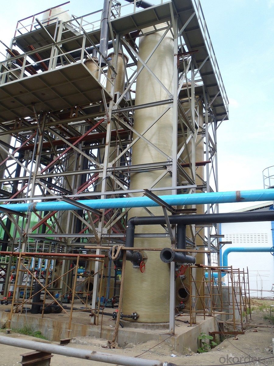
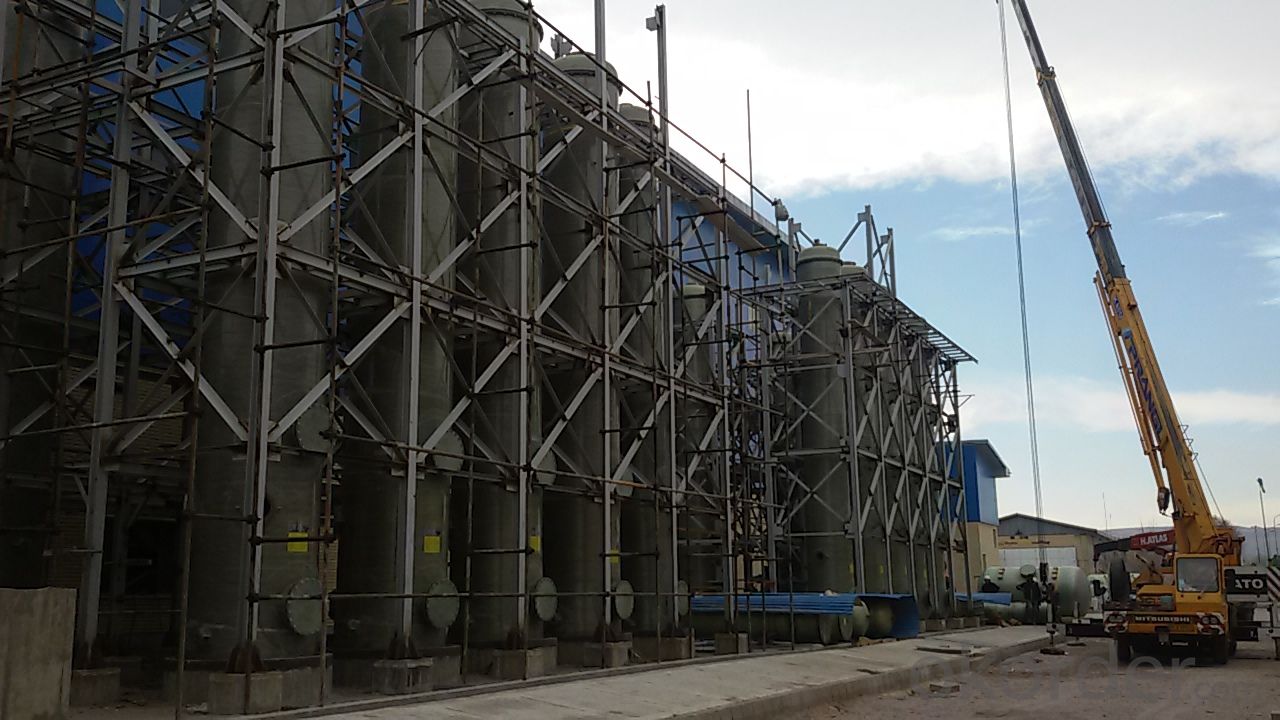
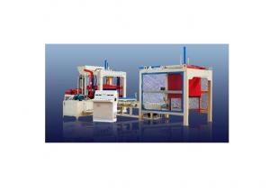
Tons of Potassium Sulfate Project
General
CNBM is a high-tech enterprises international chemical engineering company, who is pioneering in chemical engineering technologies, and playing a leading role in new technology development, with capability of project consulting, design,procurement, construction management and production guidance. CNBM provide services of chemical engineering and technology, with offering a scope of supply ranging from process design till the supply of completely integrated plants. CNBM master a technology of Potassium Sulfate production line, Calcium Chloride production line,sulfuric acid production line other fertilizers.We have cooperated with many international companies on projects,located Indonesia,Philippines,India,Jordan,Egypt.etc.
Equipment List for Production Line
| No | Description | Specification | Material | Power | Qty | Unit | Notes |
| A. Raw Material Feeding System | |||||||
| 1 | KCL Tank (MOP) | 1.8*1.8*1.6 | cs | 2 | pc | ||
| 2 | KCl Screw conveyor | 9t/h | cs | 5.5KW | 2 | pc | |
| 3 | KCL Bucket Elevator | 9t/h | cs | 5.5 KW | 2 | pc | |
| 4 | En masse conveyor ,KCl | 9t/h | 7.5 KW | 2 | pc | Changed according to the arrangement of the workshop | |
| 5 | Belt Conveyor, MOP | 9t/h | 2 | ||||
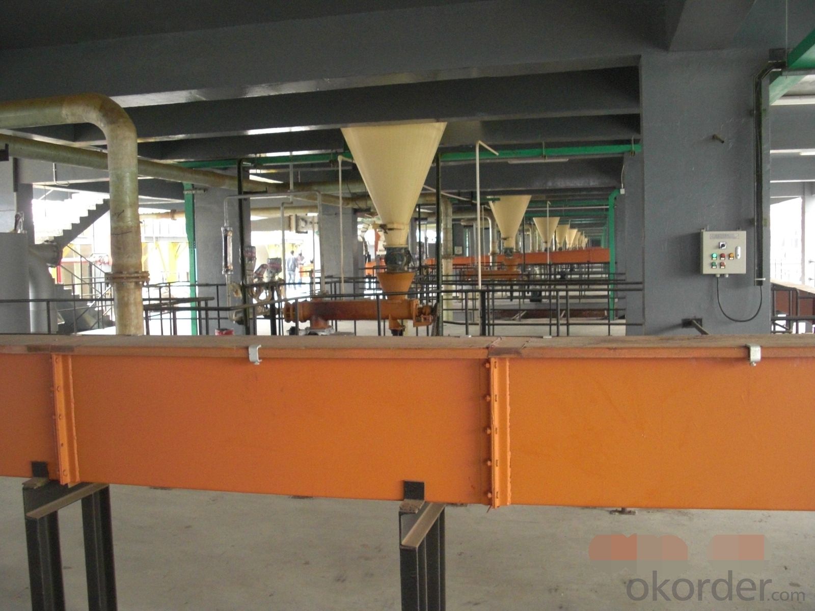
| 6 | KCl feeding bin | D1.7*2.5 | cs | 10 | pc | ||
| 7 | KCl Screw conveyor | 2t/h | cs | 2.2KW | 10 | pc | |
| 8 | Surge Tank, Sulfuric Acid | D1*1.7 | cs | 10 | pc | ||
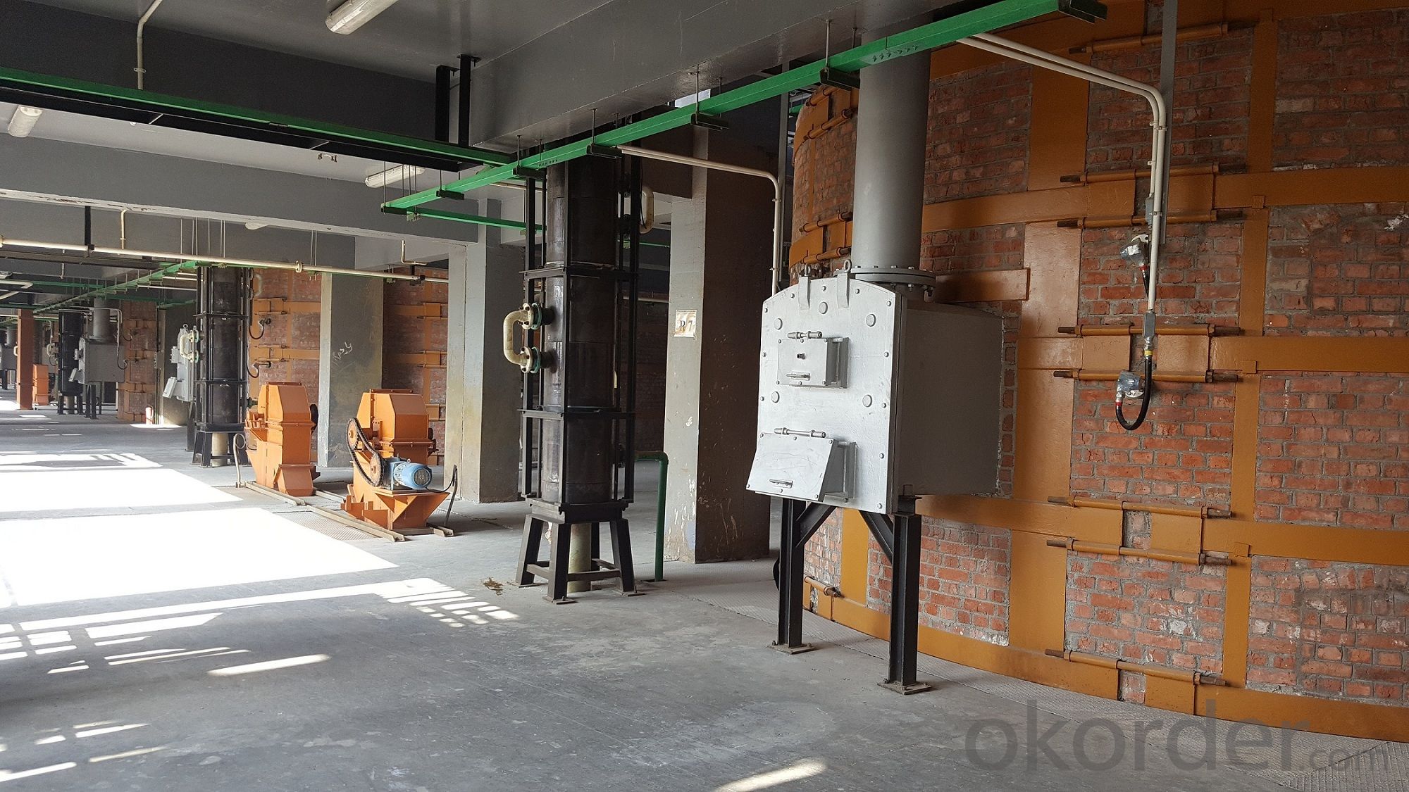
| B.Reaction Furnace and Potassium Sulfate Production System | |||||||
| 1 | Reaction Furnace include bricks Mechanical parts .Steel Structure of furnace | 10 | Set | ||||
| 2 | Main motor | 15 KW | 10 | pc | |||
| 3 | Air Induced Fan | 11KW | 10 | pc | |||
| 4 | Exhaust fan | 7.5 KW | 10 | pc | |||
| 5 | Reheater | D900×4600 | cs | 10 | pc | ||
| 6 | K2SO4 Ejector Cooler | D1.1*5.2 | cs | 7.5 KW | 20 | pc | |
| 7 | Air Seal Screw Conveyor, Product | Φ200×1600 | cs | 3 KW | 20 | pc | |
| 8 | Stack | 29m | cs | 10 | pc | ||
| C. Furnace Combustion System ( Natural Gas) | |||||||
| 1 | Burner system | 4 KW | 20 | pc | |||
| 2 | Surge Tank.Diesel fuel | 1.5KW | 20 | pc | |||
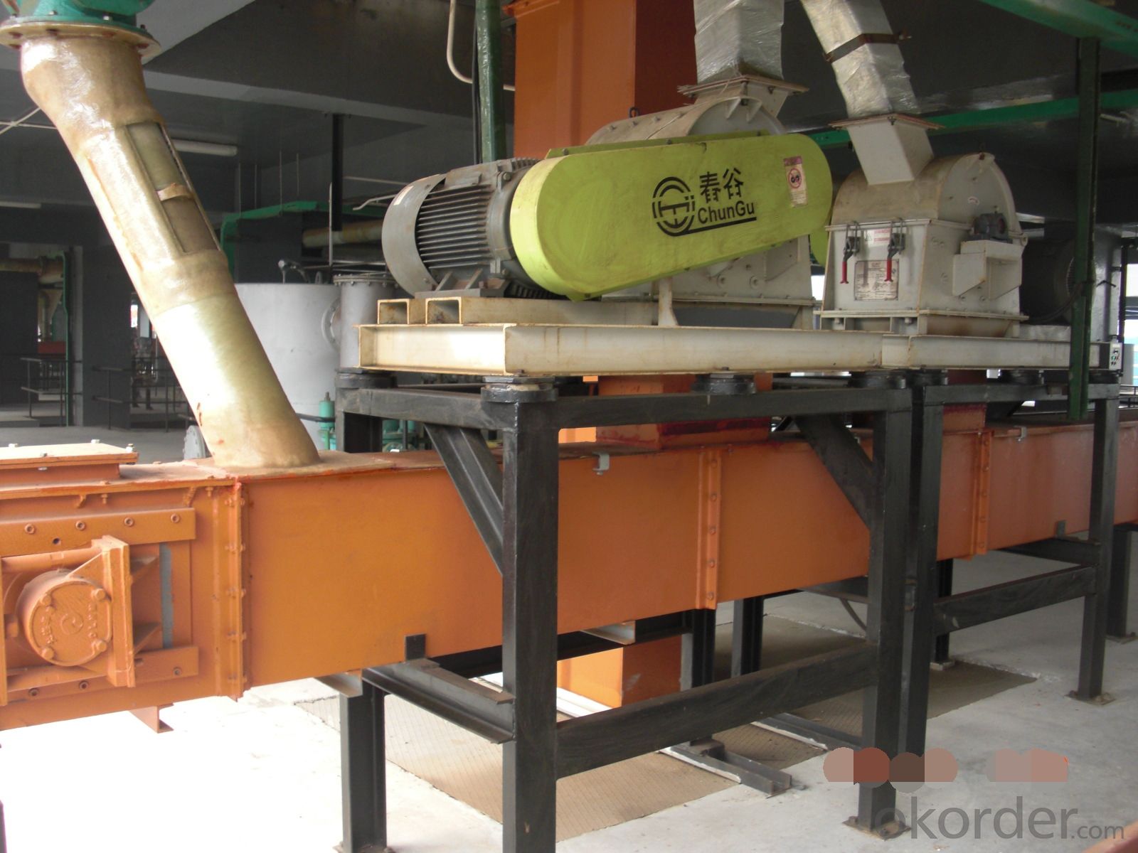
| D. Product Treatment and Handling | |||||||
| 1 | Belt Conveyor, Product | 9ton/h, | Rubber | 2 | pc | Changed according to the arrangement of the workshop | |
| 2 | Bucket Elevator | H10000mm, 3ton/h | cs | 4KW | 2 | pc | |
| 3 | Crusher | 4T/h | cs | 18.5KW | 2 | pc | |
| 4 | Vibrating screen | 4T/h | cs | 2.2+2.2kw | 2 | pc | |
| 5 | Product/En mass conveyor | 7T/h | cs | 3 KW | 2 | pc | |
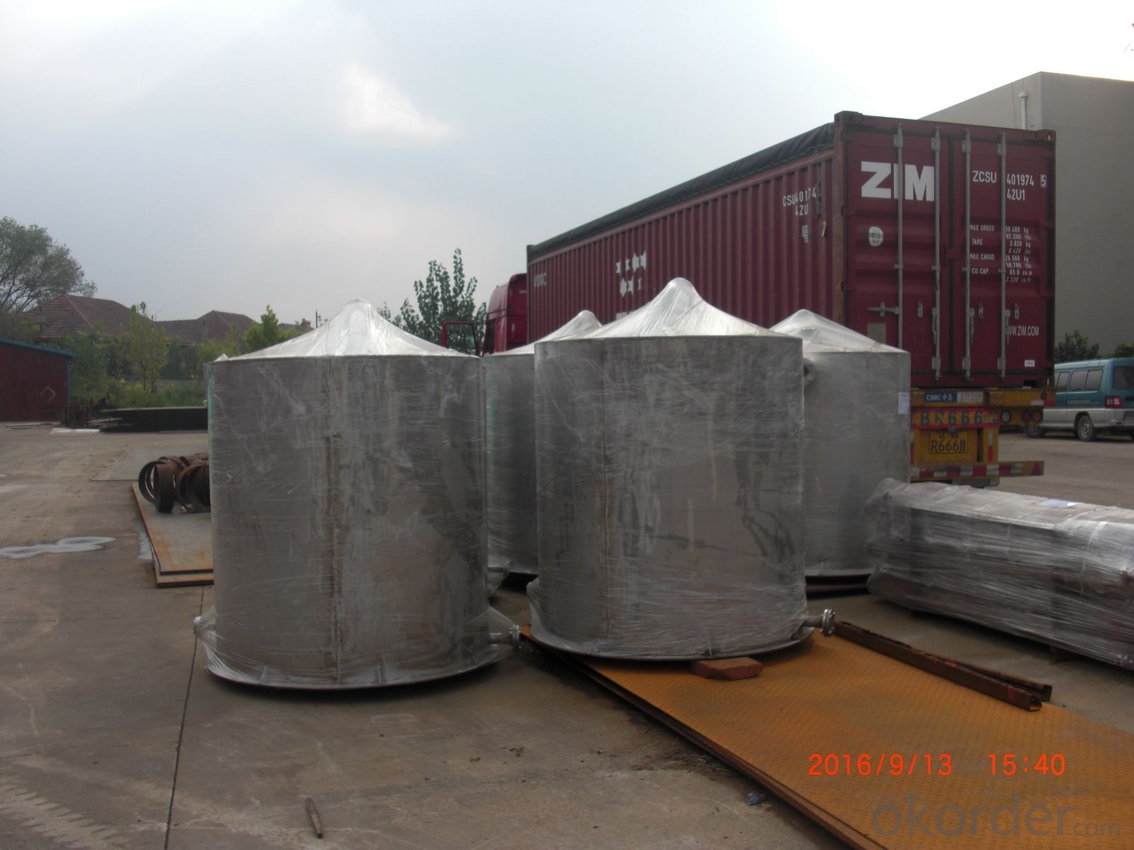
| 6 | Product Silo | 33m3 | cs | 6 | pc | By OWNER | |
| 7 | Bag Filter | 95m2 | cs | 2 KW | 2 | pc | |
| E. Scrubber and Absorber System | |||||||
| 1 | HCl gas hood | 2.0*1.5*1.4 | F.R.P | 20 | pc | ||
| 2 | Fan,environment | 3300NM3h | F.R.P | 7.5 KW | 10 | pc | |
| 3 | Scrubber, Environment | D1.4*11, 20 m3/h circ. | F.R.P | 10 | pc | ||
| 4 | Graphite Cooler | D0.47*4.1A=25 m2 | Graphite | 10 | pc | ||
| 5 | Scrubber 1 | D1.4*11, 20 m3/h circ. | F.R.P | 10 | pc | ||
| 6 | Scrubber 2 | D1.4*11, 20 m3/h circ. | F.R.P | 10 | pc | ||
| 7 | First Absorber | D0.75*4.3, A=25 m2 | Graphite+FRP | 30 | pc | ||
| 8 | Second Absorber | D0.75*1.6, 0.7m3 | F.R.P | 30 | pc | ||
| 9 | Scrubber, HCL Gas | D1.4*11, 20 m3/h circ. | F.R.P | 30 | pc | ||
| 10 | Defogger | D0.5*1.345, 0.24m3 | F.R.P | 10 | pc | ||
| 11 | Fan, HCl Gas | 3000Nm3/h | F.R.P | 20 | pc | ||
| 12 | Stack of HCL tail gas | D0.3×1.5 | F.R.P | 2 | pc | ||
| 13 | Dilute Acid Gravity Tank | D1.2*1.6 | F.R.P | 5 | pc | ||
| 14 | Fan, HCl Gas | F.R.P | 7.5 | 10 | pc | ||
| 15 | Dilute Acid Gravity Tank | D1.2*1.6 | F.R.P | 5 | pc | ||
| 16 | Surge Tank, HCl | D2.0*3.5,10M3 | FRP | 10 | pc | ||
| 17 | Pump, HCl | H=30M,q=25m3/h | 70 | pc | |||
| 18 | FRPP Stack | D0.3*19 | FRPP | 5 | pc | ||
| 19 | Process Water Gravity Tank | D2*2.5 | FRP | 5 | pc | ||
| 20 | Graphite Cooler | D0.3*1.1A=5M2 | Graphite | 10 | pc | ||
| 21 | Graphite Cooler | D0.4*1.3A=8M2 | Graphite | 6 | pc | ||
| F. Utility Circulate Water System | |||||||
| 1 | Cooling Tower | 500m3/h,∆T>10°C | FRP | 2 | pc | ||
| 2 | Hot Water Pump | 3 | pc | ||||
| 3 | Pump,Water Supply | 3 | pc | ||||
| 4 | Backwater bucket | 1.3*0.6*0.65 | 10 | pc | |||
| 5 | Sulfuric acid Tank | 100m3 | cs | 5 | pc | If necessary,,by owner | |
| 6 | Sulfric acid pump | 2m3/h,H=20m | 2 | pc | If necessary ,by owner | ||
| 7 | HCl tank | 100m3 | F.R.P | 20 | pc | If necessary, by owner | |
| 8 | HCl pump | 25m3/h,H=20m | 4 | pc | If necessary, by owner | ||
| 9 | Diesel Tank | 30m3 | cs | 1 | pc | If necessary by owner | |
| 10 | Diesel pump | 1m3/h,H=10m | 2 | pc | If necessary by owner | ||
| 11 | Alkaline tank | 5m3 | cs | 2 | pc | If necessary by owner | |
| G. Pipes and Fittings | |||||||
| H. Electrical | |||||||
| 1 | Motor Control Center | MCC | 1 | ||||
| 2 | Cabling system | ||||||
| I. Instrumentation | |||||||
| 1 | Instrument and gauge | ||||||
| 2 | Cabling system | ||||||
| J: DCS | |||||||
| 1 | DCS software and operating station | ||||||
| 2 | DCS cabinet system | ||||||
1. SA Storage tank, HCL storage tank, Utilities (cooling water system, natural, compressed air, etc) and packaging system is not included.
2. Installation material and support of plant and equipment is not included.
3. The equipment should be changed according to the design and layout of the plant.
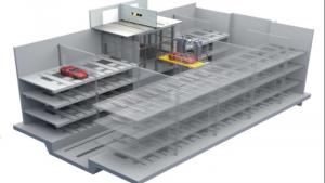
3D soft ware:
 Project Potassium sulfate factory")
 Project Potassium sulfate factory")
 Project Potassium sulfate factory")
 Project Potassium sulfate factory")
 Project Potassium sulfate factory")