Loading Port:Nanjing
Payment Terms:TT OR LC
Min Order Qty:200000 watt
Supply Capability:20000000 watt/month
INTRODUCTION
This installation Manual contains essential information for the electrical and mechanical installation that your must know before installing CUSTOMER PV modules. This also contains safety information you need to be familiar with .All the information described in this manual are the intellectual property of CNBM and based on the technologies and experiences that have been acquired and accumulated in the long history of CUSTOMER. This document does not constitute a warranty, expressed or implied.
CUSTOMER does not assume responsibility and expressly disclaims liability for loss, damage, or expense arising out of in anyway connected with installation, operation, use or maintenance of the PV modules. No responsibility is assumed by CUSTOMER for any infringement of patents or other rights of third parties that may result from use of PV module.
CUSTOMER reserves the right to make changes to the product, specifications or installation manual without prior notice.
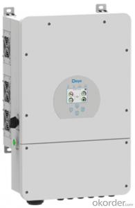
WORK PRINCIPLE

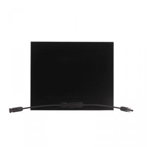
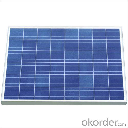
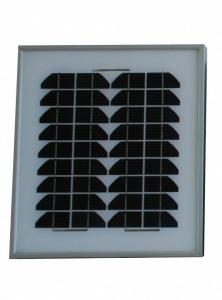
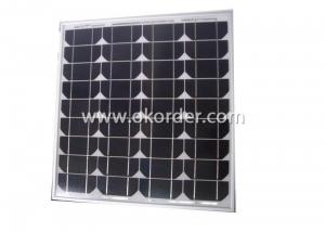
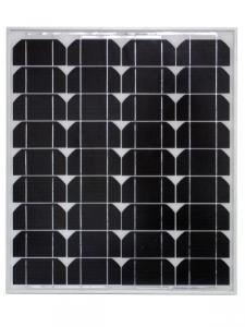
COMPONENTS

WIRING
To ensure proper system operation to maintain your warranty, observe the correct cable connection polarity(Figures 1&2) when connecting the modules to a battery or to other modules. If not connected correctly, the bypass diode could be destroyed.
PV modules can be wired in series to increase voltage. Connect wires from the positive terminal of one module to the negative of the next module. Figure shows modules connected in series .

GROUDING
All PV models must be grounded by electrical connection of the module frames to ground. Please be careful in arranging the system ground so that the removal of one module from the circuit will not interrupt the grounding of any other modules.
The modules should be grounded to the same electrical point as described below.
Each PV module has a hole on the side frame of either a bolt, nut and washer grounding the module to the frame, a ground lug fastened by bolt or screw, or appropriate screw(hardware not provided).An example of acceptable ground connection using a bolt, nut and washer retaining a ground lug is shown in figure 3,in a connection of this type, the hardware(such as a toothed locked washer/star washer) must score the frame surface to make positive electrical contact with the frame. The ground wire must be considered within the requirement of local and regulation at the site of installation.

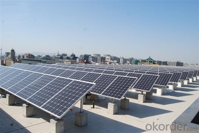
MOUNTING
Please make sure that all the information described in the installation manual is still valid and proper for your installation. The mounting method has been verified by CNBM and NOT CERTIFIED by a third party organization.
The approved way to mount CNBM PV modules to a support structure is using the bolt holes provided as described in the Specifications. Although CNBM does not specify or warrant frame clips or clamps, using frame clips (not provided ) or clamps module (not provided ) is also possible when they are designed for PV modules and with minimum dimensions on the sides of the module in accordance with the instructions and drawings provided. If using frame clips or clamps, the modules should be fixed rigidly and there shall be no damage to the modules by deforming mounting structure against design load. CNBM does not specify or warrant frame clips. The CNBM module warranty may be void if customer-selected trame clips which are improper or inadequate with respect to the module properties(including strength or material)or installation. Note that if metal clips are used, there must be a path to ground from the clips.(for instance, using star washers in the clip hardware set). Please review the descriptions and drawings carefully; not mounting the modules according to one of these methods may void your warranty. These mounting methods are designed to allow module loading of 2400pa.