Loading Port:China Main Port
Payment Terms:TT OR LC
Min Order Qty:-
Supply Capability:-
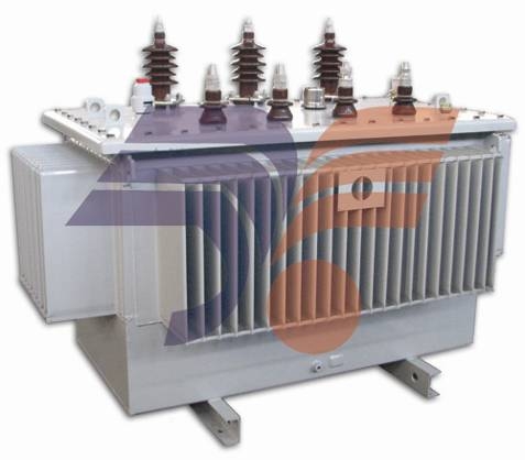
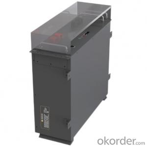
SH15-M Series
Amorphous Alloy Oil-immersed Transformer

Introduction of Products
Amorphous alloy isderived from iron, boron and other elements which rapid cooling down to mouldin order to arrange its atoms disordered. Compared with silicon sheets, the permeabilityof amorphous alloy is high, the no-load losses and current is lower, and moreoperation charges can be saved. Meanwhile, its heat is low,and it has good stability to make its working lifelonger.
Performance Characteristics
1. Saving power: The no-load losses reduce byabout 80% than that of S9 series.
2. Reliable: The capability of anti-shortcircuit is strong.
3. Protecting environment: Its noise is lowand it can decrease the discharging quantity of carbon.
Structure Characteristics
1. The core adopts three-phase five-limb and HV winding adopts D connection,which eliminates the three fluxes and three-harmonic electric potential anddecrease eddy current loss and temperature caused by leakage. Meanwhile, the steepnessof impulse voltage is reduced.
2. The coil takesthe shape of rectangular, and use conductor tensioning device to wind. Itadopts shaping, press mounting and other technique measures to make the outsidedimension of coil come to design requirement. And that HV coils wind outside LVcoils improve the strength of coil and the capability of anti-short circuit.
3. There is no oilstorage tank and moisture absorber on the oil tank. The transformer oil doesn’tcontact with the air and the expansion of oil depends on the elasticity of corrugatedplates to compensate. This can eliminate maintenance and improve working life.
Normal Using Condition
1. The altitude is not more than 1000m.
2. Environment temperature
Highest temperature: +40℃
Hottest monthly average temperature: +30℃
Highest yearly average temperature: +20℃
Lowest temperature: -40℃
3. Using outdoors( or indoors)
4. The wave shape of supply voltage is approximateto sine wave.
5. The supply voltage of three phases isgenerally symmetric.
If thetransformers need to be used at abnormal condition, the details should beoffered when the users order.
Main Specification and Technology Parameter
1. Range of rated capacity: 50~2500kVA
2. Rated voltage: not more than 10kv
3. Rated frequency: 50Hz
4. Insulating level
Voltage Grade (kv) | The highest voltage effective value of equipment(kv) | Rated short-time applied withstand voltage(kV/min) | Rated lightning impact withstand voltage(peak)(kv) |
≤1 | 1.1 | 3 | -- |
6 | 7.2 | 20 | 60 |
10 | 12 | 35 | 75 |
5. The insulating classof transformer is A, coil temperature rise is not more than 65K, and thetemperature rise of top oil is not more than 60K.
6. Thetransformers correspond with the following standards:
a. GB1094.1~2, GB1094.3, GB1094.5 Power transformer
b. JB/T 10318 Technology parameter and request of oil-immersedamorphous alloy core distribution transformer
c. Standard of InternationalElectro-technical Commission: IEC60076, Power transformer
d. Q/SIHG1 SH15-M Technology parameter andrequest of three-phase oil-immersed distribution transformer of amorphous alloycore sealed type
7. TechnologyParameter of SH15-M Series
Rated capacity (kVA) | Voltage and tapping range | Symbol of connecting group | No-load losses (W) | Load losses (W) | No-load current (%) | Impedance of short circuit (%) | ||
HV(KV) | Tapping range (%) | LV(kV) | ||||||
30 |
6 6.3 10 10.5 11 |
±5 ±2x2.5 |
0.4 |
Dyn11 | 33 | 630 | 1.7 |
4 |
50 | 43 | 910 | 1.3 | |||||
63 | 50 | 1090 | 1.2 | |||||
80 | 60 | 1310 | 1.1 | |||||
100 | 75 | 1580 | 1 | |||||
125 | 85 | 1890 | 0.9 | |||||
160 | 100 | 2310 | 0.7 | |||||
200 | 120 | 2730 | 0.7 | |||||
250 | 140 | 3200 | 0.7 | |||||
315 | 170 | 3830 | 0.5 | |||||
400 | 200 | 4520 | 0.5 | |||||
500 | 240 | 5410 | 0.5 | |||||
630 | 320 | 6200 | 0.3 |
4.5 | ||||
800 | 380 | 7500 | 0.3 | |||||
1000 | 450 | 10300 | 0.3 | |||||
1250 | 530 | 12000 | 0.2 | |||||
1600 | 630 | 14500 | 0.2 | |||||
2000 | 750 | 17400 | 0.2 |
5 | ||||
2500 | 900 | 20200 | 0.2 | |||||
Outline Dimension
Type | Outside dimension (mm) | Weight (kg) | |||
Length | Width | Height | Oil weight | Total weight | |
SH15-30 | 1100 | 690 | 1090 | 130 | 630 |
SH15-50 | 1190 | 750 | 1140 | 160 | 710 |
SH15-63 | 1250 | 750 | 1160 | 160 | 750 |
SH15-80 | 1290 | 750 | 1200 | 170 | 810 |
SH15-100 | 1260 | 800 | 1190 | 180 | 870 |
SH15-125 | 1320 | 810 | 1220 | 190 | 940 |
SH15-160 | 1370 | 810 | 1220 | 210 | 1050 |
SH15-200 | 1410 | 800 | 1320 | 230 | 1140 |
SH15-250 | 1490 | 810 | 1360 | 260 | 1290 |
S(B)H15-315 | 1520 | 790 | 1430 | 280 | 1500 |
S(B)H15-400 | 1670 | 820 | 1510 | 330 | 1710 |
S(B)H15-500 | 1650 | 910 | 1450 | 370 | 1960 |
SBH15-630 | 1830 | 920 | 1440 | 430 | 2250 |
SBH15-800 | 1910 | 950 | 1500 | 480 | 2730 |
SBH15-1000 | 2000 | 1100 | 1490 | 620 | 3330 |
SBH15-1250 | 2100 | 1100 | 1580 | 730 | 3560 |
S(B)H15-1600 | 2120 | 1240 | 1560 | 860 | 3830 |
A comparison about no-load losses of amorphous alloyand silicon sheet
Capacity (KVA) | No-load losses (w) | |
S9 type (silicon sheet) | SHI5 type (amorphous alloy) | |
100 | 290 | 75 |
315 | 670 | 170 |
500 | 960 | 240 |
The Manufacturing Process of Amorphous Alloy Materials
a. The raw materials melt in the induction furnace.
b. The melted materials are transferred to feedingpart.
c. Control of casting head
d. After melting to be thin, it is sprayed to coolingwheel.
e. The sprayed materials cool down at the speed of 106℃ per second to form amorphous alloybelt.
f. Measure the width and thickness of alloy belt andfeedback to control system.
g. It is led to pull through unit.
h. Material receiving
A comparison to manufacturingprocess of amorphous alloy and silicon sheet
Amorphous alloy material Orientation silicon sheet

Social and Economic Effects
The manufacturingprocess of core materials of amorphous alloy core transformers is simple, andthe energy source losses are little, so the carbon discharge can be reduced.
No load losses are low, and the increased investment cost of transformers can be taken back within5 years.
Low operation temperature, small insulation deterioration, long working life.
The ordering basic data
1、Rated capacitance;
2、Rated voltage;
3、Rated frequency;
4、Tapping range;
5、Impedance voltage;
6、Using condition;
7、Other performance data should be indicated inthe contract.