Loading Port:Ningbo
Payment Terms:TT OR LC
Min Order Qty:1 unit
Supply Capability:10 unit/month
It is also possible to replace the standard diode-bridge rectifier with a bi-directional IGBT switching device bridge mirroring the standard inverter which uses IGBT switching device output to the motor. Such rectifiers are referred to by various designations including active infeed converter (AIC), active rectifier, IGBT supply unit (ISU), active front end (AFE), or four-quadrant operation. With PWM control and a suitable input reactor, an AFE's AC line current waveform can be nearly sinusoidal. AFE inherently regenerates energy in four-quadrant mode from the DC side to the AC grid. Thus, no braking resistor is needed, and the efficiency of the drive is improved if the drive is frequently required to brake the motor.
Two other harmonics mitigation techniques exploit use of passive or active filters connected to a common bus with at least one VFD branch load on the bus. Passive filters involve the design of one or more low-pass LC filter traps, each trap being tuned as required to a harmonic frequency (5th, 7th, 11th, 13th, . . . kq+/-1, where k=integer, q=pulse number of converter).
It is very common practice for power companies or their customers to impose harmonic distortion limits based on IEC or IEEE standards. For example, IEEE Standard 519 limits at the customer's connection point call for the maximum individual frequency voltage harmonic to be no more than 3% of the fundamental and call for the voltage total harmonic distortion (THD) to be no more than 5% for a general AC power supply system.
The carrier-frequency pulsed output voltage of a PWM VFD causes rapid rise times in these pulses, the transmission line effects of which must be considered. Since the transmission-line impedance of the cable and motor are different, pulses tend to reflect back from the motor terminals into the cable. The resulting voltages can produce overvoltages equal to twice the DC bus voltage or up to 3.1 times the rated line voltage for long cable runs, putting high stress on the cable and motor windings, and eventual insulation failure. Note that standards for three-phase motors rated 230 V or less adequately protect against such long-lead overvoltages. On 460 V or 575 V systems and inverters with 3rd-generation 0.1-microsecond-rise-time IGBTs, the maximum recommended cable distance between VFD and motor is about 50 m or 150 feet. Solutions to overvoltages caused by long lead lengths include minimizing cable distance, lowering carrier frequency, installing dV/dt filters, using inverter-duty-rated motors (that are rated 600 V to withstand pulse trains with rise time less than or equal to 0.1 microsecond, of 1,600 V peak magnitude), and installing LCR low-pass sine wave filters. Regarding lowering of carrier frequency, note that audible noise is noticeably increased for carrier frequencies less than about 6 kHz and is most noticeable at about 3 kHz. Note also that selection of optimum PWM carrier frequency for AC drives involves balancing noise, heat, motor insulation stress, common-mode voltage-induced motor bearing current damage, smooth motor operation, and other factors. Further harmonics attenuation can be obtained by using an LCR low-pass sine wave filter or dV/dt filter.
See also: Dynamic braking and Regenerative braking
Torque generated by the drive causes the induction motor to run at synchronous speed less the slip. If the load drives the motor faster than synchronous speed, the motor acts as a generator, converting mechanical power back to electrical power. This power is returned to the drive's DC link element (capacitor or reactor). A DC-link-connected electronic power switch or braking DC chopper controls dissipation of this power as heat in a set of resistors. Cooling fans may be used to prevent resistor overheating.
Dynamic braking wastes braking energy by transforming it to heat. By contrast, regenerative drives recover braking energy by injecting this energy into the AC line. The capital cost of regenerative drives is, however, relatively high.

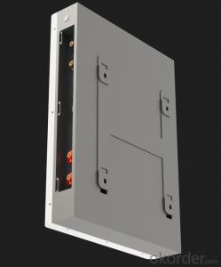
Line regenerative variable frequency drives, showing capacitors (top cylinders) and inductors attached, which filter the regenerated power.

Simplified Drive Schematic for a Popular EHV
Regenerative AC drives have the capacity to recover the braking energy of a load moving faster than the designated motor speed (an overhauling load) and return it to the power system.
Cycloconverter, Scherbius, matrix, CSI, and LCI drives inherently allow return of energy from the load to the line, while voltage-source inverters require an additional converter to return energy to the supply.
Regeneration is useful in VFDs only where the value of the recovered energy is large compared to the extra cost of a regenerative system, and if the system requires frequent braking and starting. Regenerative VFDs are widely used where speed control of overhauling loads is required.
Some examples:
Conveyor belt drives for manufacturing, which stop every few minutes. While stopped, parts are assembled correctly; once that is done, the belt moves on.
A crane, where the hoist motor stops and reverses frequently, and braking is required to slow the load during lowering.
Plug-in and hybrid electric vehicles of all types